|
StuccoMetrics® |
Jeff Bowlsby CCS, CCCA
Exterior Wall and Stucco Consultant
Licensed
California Architect
Stucco Shrinkage Movement Joint
Subassembly (SMJS)
(“control joint”)
|
Webpage Quicklinks Terminology: "Control Joint" vs. SMJS
Subassembly Portland Cement-based Plaster
and Stucco Movements Purpose of the SMJS
Subassembly SMJS Subassemblies, Water
Intrusion and Water Management Open Stud Framing as Substrate Support Panelized
Sheathing over Framing as Substrate Support Substrate
Support Planar Tolerance and Shims Performance
Testing including Variant SMJS Subassembly Configurations Alternate Materials,
Designs, Tests and Methods of Construction Omission of SMJS Subassemblies Decorative Joint (DJ) Subassembly SMJS Subassembly at Panel Edges SMJS Subassembly within Panel Areas Horizontally-oriented SMJS Subassembly on Walls Vertically-oriented SMJS Subassembly on Walls Horizontal and Vertical Intersections Sealant at Splices, Terminations, Intersections Low-Slope
Weather-Exposed Surfaces A Case Study: Bringing
It All Together To Minimize Cracks Detail Drawings - SMJS Subassembly |
||||||||||||||||||||||||||||||||||||||||
|
This
webpage is dedicated to my ASTM C11 Committee colleagues To
determine which stucco movement joint is appropriate for a given condition,
one must understand the anticipated movement at the condition. Shrinkage and thermal movements occur in
the lath and stucco membrane. BMJS,
PMJS and SMJS each accommodate shrinkage and thermal movements because the
lath and stucco composite membrane is discontinuous through and terminate at
each side of these subassemblies. A
SMJS does not accommodate substrate support movement because the substrate
support is continuous at SMJS. BMJS
and PMJS accommodate substrate support movement because the substrate support
is discontinuous at these subassemblies.
Stucco Movement Joint
Selection Matrix Everyone
interested in exterior stucco wall cladding systems has a perspective on
“control joints” and those perspectives are not unilaterally held by
all. The vast array of information
about “control joints” can easily perplex and overwhelm, and the industry is
replete with a variety of differing viewpoints and oftentimes conflicting,
incomplete, inaccurate or obsolete information. Much of the information being circulated
and relied upon today was developed many years ago, and while perhaps based
on the best information available at the time, stucco research and technology
has advanced since then and now some of that information is obsolete or
better quality information is available.
Some current resources have innocently parroted other resources,
continuing the spread of conflicting, incomplete, inaccurate or obsolete
information and base opinions on this lack of correct information which is
unfortunate and is one cause of much strife in the industry on this
subject. We have the capability and
information available now to discern myths from reality. The
term “control joint” is vague and ambiguous and does not describe its primary
function initiating endless debates about what it is, what it does and how it
does it. The replacement term
Shrinkage Movement Joint Subassembly (SMJS) is used on this website which is
intended to better convey its essential association with shrinkage movement,
and significantly identify its role as a subassembly of a larger stucco wall
cladding system. A “control joint” is
not just a lath accessory bolted onto a wall.
It is a primary purpose of this webpage and website to convey
reasonable, credible, rationally-based and defensible information leading to
an understanding of the primary purposes of the SMJS subassembly, how it is
intended and required to function, and how it actually does function, that it
is hoped will resolve any lingering debate about its design, installation and
location requirements to be an effective stucco wall cladding subassembly
that serves its primary function towards minimizing stucco cracks. The SMJS subassembly, its intended purpose, function, and installation
configuration can be misunderstood amongst building owners, architects and
craftsman. If cracking did not occur,
stucco would be much more popular, respected and prolifically used as an
exterior wall cladding. These are the
intended outcomes of these webpages regarding stucco movement joints. Portland
cement-based plaster shrinkage and stucco thermal
movements are real and known causes of stucco cracking. If exterior stucco wall cladding systems
did not experience shrinkage or thermal movements,
then there would be only limited purpose for the SMJS subassembly. This webpage attempts to unpack and
evaluate the plethora of accurate and inaccurate information in circulation
and provide a rational, factual basis for providing correctly assembled,
functioning SMJS subassemblies, including information on SMJS subassembly
history, design, lath accessory and subassembly configuration requirements,
performance testing and the capabilities and limitations of the SMJS
subassembly that are useful towards minimizing stucco cracking and water
intrusion. Where the SMJS subassembly is the
primary means of accommodating cement-based plaster shrinkage and stucco thermal
movements, it is only when the SMJS subassembly is correctly located within a
stucco wall cladding system relative to wall openings and larger wall
expanses, and configured into panel areas of certain dimensions and
geometries that it creates a functional cement-based plaster shrinkage and
stucco thermal movement control Assembly.
While this webpage focuses on the SMJS subassembly it also covers the
essential parameters for a portland cement-based plaster shrinkage and stucco
thermal movement control Assembly. If a stucco wall cladding system did not
experience shrinkage and thermal movements, then there would be no essential
purpose for the SMJS subassembly. This
webpage explores the conditions that make the SMJS subassembly beneficial to
the success of an exterior stucco wall cladding system on a building as a
substrate support. Visit the StuccoMetrics Reference Archives
webpage for cited references and further information. |
||||||||||||||||||||||||||||||||||||||||
|
From Technical Manual, Keene
Corporation, Penn Metal Products, c.1980 From the earliest times when portland cement-based plaster first
began to be applied onto framed building structures, the biggest concern was
wall opening corner cracking at reentrant window/door corners. In the late 1910’s through early 1920’s,
the US Bureau of Standards, as part of the Department of Commerce, performed
a battery of testing on portland cement-based plaster and stucco wall
cladding and its Components because it recognized the potential and
importance of stucco to the economy and wanted to assist in its success as a
building material. The Bureau of
Standards constructed several full-sized test buildings with multiple test
panels of stucco to test and observe the performance of various combinations
of stucco components, lath types and materials, stucco mortar mix designs,
framing/sheathing type alternatives, and application and curing methods for
optimum results and minimized cracking.
A significant part of the stucco testing at this time was devoted to
evaluating the predominant stucco cracking conditions occurring at window
corners. During this era, stucco
cracking was most commonly attributed to building structure movements. Soil settlement and wind loads were also
suspected causes of cracking. Further
government testing determined that wood lath was a major cause of stucco
cracking and was ultimately replaced in the marketplace by expanded sheet
metal lath and wire lath. Various
board sheathing types and installation methods (to minimize building
movements) were evaluated, ultimately determining that horizontally-installed
board sheathing was the best method for sheathing a building for stucco
cladding to minimize reentrant window/door corner cracking. Yet despite these improvements, reentrant
corner stucco cracking persisted.
1916 US Bureau of Standards Stucco
Testing to evaluate window corner and stucco
panel cracking Patent research: Not all SMJS lath accessory components are patented and not all patented SMJS lath accessory components were produced or are currently available. Select SMJS lath accessory components and subassemblies are discussed.
In 1920, inventor John Earley (who had participated in the Bureau of Standards testing
program) devised the first stucco movement joint lath accessory and SMJS
subassembly, Patent No. 1355756, Flexible
Joint for Stuccoed Buildings, for a flexible
metal joint screed lath accessory for use around window and door frames. Earley opined that
a building and stucco cladding were stable using board sheathing, therefore
stucco only cracked because the wood window/door frames and underlying
framing at these wall openings expanded due to water absorption and swelling
during seasonal wet/dry cycles, which put force on the stucco at window and
door corners, causing reentrant corner cracking. Earley’s screed
was intended to provide a safety compression zone and counteract the
window/door frame expansion forces, and prevent stucco cracking that was
prevalent at reentrant window and door corners. Yet reentrant corner stucco cracking
persisted.
First
stucco lath accessory patent to
address stucco cracking J.J. Earley, 1920 In the late 1940’s a serious stucco cracking problem was
reported to have developed at the massive Grand Cooley Dam project(1),
and the stucco community benefitted once again from a rigorous stucco system
testing program, underwritten by taxpayers.
Interior room suspended stucco ceilings cracked objectionably when
their lath was continuous through the ceiling/wall juncture and secured to
the adjacent concrete perimeter walls (the common practice of the day). It was discovered through extensive testing
of many variables, that the ceilings did not crack when the lath was
discontinuous at the ceiling/wall juncture, which allowed the ceilings to
shrink away from the walls. The
perimeter ceiling gaps that developed when the ceilings were isolated and
shrank away from the walls were large and measurable, but no ceiling cracking
occurred attributable to the isolated perimeter lath condition which was
deemed to be of great benefit in minimizing cracking at the ceilings. Discontinuous lath, which eliminated restraint conditions at
stucco ceiling panel perimeters of interior rooms, was
proven to minimize stucco cracking at Grand Coulee Dam. At Grand Coulee Dam lath
and stucco was installed as an unrestrained composite panel, which
accommodated shrinkage and thermal movements and minimized stucco cracking at
interfaces of different substrate supports.
The realized benefit of this newly developed discontinuous
method of lath installation became the new paradigm for stucco on framed
substrate supports to minimize cracking:
Stucco on framed substrate supports performed better with less
cracking when constructed as adjacent, discrete, segmented panels that
accommodate shrinkage and thermal movements within each panel, as compared to
a single, non-segmented, solid, continuous lath and stucco composite mass
cladding the entire building. The
stucco movement joint subassemblies pertaining to transitions between
different substrate support materials or loadbearing conditions, or building
substrate movement conditions are known on this website and BMJS and PMJS
subassemblies. Stucco movement joints
pertaining only stucco cladding shrinkage and thermal movement where the
substrate support is continuous and produces no substrate movement, is known
on this website as a Shrinkage Movement Joint Subassembly (SMJS). The SMJS subassembly was formed by adjacent
casing beads with discontinuous lath, which is a SMJS subassembly still
recognized by Minimum Stucco Industry Standards today. By the mid-1950’s portland cement-based plaster shrinkage and
stucco thermal movement were recognized causes of cracking. The one-piece stucco SMJS lath accessory
component was developed and brought to market as a more convenient form than
the two-casing bead configuration. The
one-piece SMJS lath accessory component invented by Raymond Clark(2)
was filed for Patent No. 3,015,194 in 1955, and the patent was granted in
1962. This product is known today as
the Double-V lath accessory, and generically as a SMJS lath accessory
component on this website. The
Double-V SMJS lath accessory component features an expansible, resilient
pleat at its center with expanded sheet metal flanges to each side for keying
the SMJS lath accessory component to the adjacent lath edges as the result of
discontinuous lath. The anticipated
behavior of the continuous lath was described in numerous locations
throughout the patent as “expansible” and was considered to be the primary
zone of movement along with the pleat of the lath accessory component. The SMJS lath accessory component is of a
vertical height dimension sufficient to function as a plaster thickness
ground screed and its configuration provides a convenient location to stop
plastering work where needed, to avoid the need for “joinings” (cold joints)
in the plaster. The Penn Metal
Company, and later the Keene Corporation and Metalex which later acquired
Penn Metal Company, were the original manufacturers of this original
one-piece SMJS lath accessory component.
Illustrations from
Clark Patent 3,015,194 (Note
the patent illustrates both a SMJS lath accessory component and
SMJS subassembly. The SMJS lath
accessory is wire-tied to continuous lath.
Arrows 40 and 41 depict anticipated SMJS subassembly movement
behavior.) From
the Clark patent the SMJS lath accessory and SMJS subassembly functions as
follows: “…due to the stresses and
strains of expansion and contraction caused by initial drying, by subsequent
variations in temperature and humidity of the surrounding
atmosphere...”. “It provides narrow
gaps at desired intervals across the face of the finished coating of [stucco]
which extend through the entire thickness of the [stucco] on the lathing so
that the [stucco] is installed, not in a continuous expanse or sheet, but in
interrupted sections, which may expand and contract independently to an
extent at least adequately to prevent cracking of the [stucco]”. In
the Clark patent, the pleat is described as a “resilient fold”, it was intentionally designed and described to function
similar to an accordion – opening and closing, in response to the movements
of initial stucco shrinkage and thermal expansion and contraction while in
service. The SMJS lath accessory has
expanded sheet metal flanges which key the stucco to the lath and SMJS lath
accessory just as the lath does; it creates a flexible extension of the lath,
in the plane of the lath. Clark termed
this invention an “expansion joint” in his patent and this term is used in
many of the Penn Metal, Keene, Metalex catalogs.
SMJS lath
accessory, Double-V A variant of the original SMJS lath accessory is the Double-V,
Internal Corner SMJS lath accessory component, developed in the early
1960’s. It is nearly identical to the
Double-V SMJS lath accessory other than its flanges are configured into a 90
degree to nest into an internal wall corner.
SMJS lath
accessory, Double-V Internal Corner Soon after the Double-V SMJS lath accessory
component was introduced, it was observed that as its center pleat opens and
closes from initial portland cement-based plaster shrinkage and stucco
thermal movements, linear, parallel gaps can form at one or both edges of the
pleat. These parallel edge gaps are an
aesthetic distraction and may allow bulk water penetration into the stucco
wall cladding system. By about 1969 Penn Metal Co. had been acquired
by the Keene Corporation and in 1978 Keene brought an improved version of the
Double-V SMJS lath accessory to market, with the proprietary designation as
the Keene XJ15-3 and generically known as the Double-J SMJS lath
accessory. The Double-J SMJS lath
accessory is identical to the Double-V SMJS lath accessory, except it has
additional locking edge flanges that grip the stucco edges of each adjacent
stucco panel on both sides of the SMJS subassembly. This locking edge capability minimizes the
parallel gaps that can form at the stucco panel edges that the Double-V SMJS
lath accessory can experience when portland cement-based plaster shrinks away
from it or stucco thermal movement occurs, and also conceals the parallel
gaps to minimize the potential for water intrusion through the parallel edge
gaps. No separate patent for this
improved lath accessory is known to exist.
SMJS lath
accessory, Double-J
SMJS lath
accessory, Double-J, PVC The
SMJS lath accessories depicted above are available from several manufacturers
today, in a variety of corrosion-resistant materials including galvanized
steel, solid zinc alloy, stainless steel, extruded PVC and are available in a
range of ground dimensions for various stucco panel thickness
requirements. Other
SMJS lath accessory inventions after Clark, were either not commercially
successful or may have been mistakenly inferred to be SMJS lath accessories,
but were intended for larger movement conditions related to substrate support
movements and therefore are considered Building Movement Joint (BMJS) lath
accessories and subassemblies as described on this website. In 2008 the SMJS lath
accessory and subassembly evolved further when Mr. Don Pilz
of Cemco brought a number of lath accessories and
water management flashings to market, including the innovative Cemco Solid Leg #15 lath accessory(3). Generically referred to as the Double-V Horizontal Drainage SMJS lath accessory, it is most similar to a Double-V SMJS lath accessory, but it
also includes a solid flange to integrate with the WRB which allows it to
function as a horizontally-oriented drainage screed flashing for stucco wall
cladding systems. This innovation is
designed for use typically as a horizontal SMJS subassembly only, for use at
design locations on walls occurring between the foundation drainage screed
and the top of wall. It has dual
function as both a horizontal drainage screed lath accessory because it is
integrated with the WRB, and as an SMJS subassembly to minimize cracking
related to shrinkage and thermal movements.
SMJS lath
accessory, Double-V Horizontal Drainage (Cemco
Solid Leg #15) From the Stucco Material Properties webpage, we learn that the combined portland cement-based plaster shrinkage movement and stucco thermal movement accounts for approximately 130-240 mils (0.13-0.24 in.) per 10 lineal feet, or 13-24 mils per lineal foot of stucco wall cladding. The Clark patent documentation clearly describes in written and
graphic form the SMJS lath accessory intended configuration and function as a
SMJS subassembly. The lath of the SMJS
subassembly expands and contracts along with the portland cement-based
plaster shrinkage and stucco thermal movements because the two are one
composite material. The new invention
was described as being applicable for both walls and ceilings and is wire-tied
to the face of the lath. The lath was
described as being “expansible” and the SMJS lath accessory was described as
being “resilient” to accommodate movement which was anticipated by Clark to
occur at SMJS subassemblies and SMJS lath accessories. It is essential to recognize and understand
that Clark devised not only the SMJS lath accessory, but also the SMJS
subassembly which includes the SMJS lath accessory in a specific installed
configuration with other components of the subassembly such as the substrate
condition, lath, fasteners and of course the cement-based plaster, a fact
often overlooked. Lath
accessory product catalogs from the Penn Metal Company, Keene Corporation and
lastly Metalex (all were the original producers of the SMJS subassembly) provide
the first glimpse of SMJS subassembly installation requirements as provided
by the manufacturer. A manufacturer’s
installation requirements for their products are generally regarded as an
authoritative resource in the construction industry. In the timeline that follows, the
requirements described remain in effect until changes and additional
requirements are noted in subsequent catalog issues. These original SMJS lath accessory
manufacturers issued installation requirements for the SMJS lath accessory
product from at least 1959 through about 2005. SMJS lath accessory manufacturers no longer
publish SMJS subassembly installation requirements. Instead, since the 2006 IBC building code
has adopted ASTM C1063, this Minimum Stucco Industry Standard is the current
authority and reference resource on SMJS subassembly installation
requirements wherever the IBC building code is in effect.
1959-2005 Penn Metal Company, Keene Corporation, and Metalex catalogs It is interesting to review and understand the progression of
“control joint” installation requirements, because they subtly changed as
they were introduced over many years from the Penn Metal Company, Keene
Corporation, and Metalex product catalogs, and to compare them to the
requirements in the ANSI and ASTM specifications of the day up through today: ·
1955: “Expansion joint” lath accessory introduced
to market, patent issued in 1962. ·
Through early
1960’s: No installation requirements
provided in product catalogs, the only guidance was described in Clark’s
patent documentation. ·
1964: Maximum spacing for “control joints” is
“generally 8 feet.” Solid zinc lath
accessory was made for salt laden environments. ·
1971: “Install
“joints” at all locations where panel sizes or dimensions change. Joints shall extend the full width or
height of the plaster membrane.” ·
1973: Locate “control joints” where dissimilar
materials join, where substrates support conditions change such as suspended
ceilings to perimeter walls, 100-125 SF areas maximum, above door bucks and
into the ceiling juncture on both sides of heavy frames or where heavy doors
and hard use will be encountered.
Maximum panel geometry 2-1/2 to 1.
“All (Plaster-Stucco) expansion joints shall be installed…to provide a
movement capacity of 1/4 in.” ·
1974: Only zinc shall be used at exterior
locations, and the following requirements:
·
1978:
1978: Note discontinuous lath,
separate (doubled) studs, no sheathing, “control joint” lath
accessory wire-tied or nailed to/through lath edges and
into studs ·
1983: Expansion joints must be placed at least
every 100 SF and above door bucks as noted previously. Intersections of joints may be
butted-and-calked and the following:
From 1983 Keene
Corporation catalog
1983 Keene
Corporation product data (Note
discontinuous lath, separate (doubled) studs, discontinuous sheathing, fasteners
for “control joint” lath accessory not indicated) ·
1985: “Joint materials must be held firmly to metal
lath or separate (double) studs with wire ties, nails or staples.” ·
1990: Maximum panel area recommendation, 100 SF
(not 144SF), square, and aligned with wall opening corner:
From 1990’s Keene
Corporation Catalog (Note
SMJS aligning at door opening corner, panel
area size and geometry) F ·
1994-2005: Where vertical and horizontal “control
joints” intersect, the vertical joint should remain continuous and
unbroken. Screws are not mentioned as
an acceptable fastener either for lath edge fastening or fastening the
“control joint” lath accessory. ·
Sometime after 2005
Metalex ceased providing “control joint” products direct to the market, and
hence product literature, but they continue to manufacture “control joints”
and other lath accessories and provide them to other lath accessory
manufacturers that distribute them. Keene Corporation published a Technical Manual(4), c. 1980, as a general guide to
“control joints”. Unlike other Keene
documents of the era, this document is primarily a narrative and written in a
language style more as a guide than specifying technical requirements. Interestingly, the term “control joints” is
identified and intentionally used exclusively by Keene in this document after
discussing other terms used in the era, for stated consistency reasons. None the less the manual does present the
following technical installation requirements, “…a control joint…must be
used...”: ·
Where dissimilar
materials join ·
Where a large
suspended ceiling is pierced by supporting beams or columns ·
“Where
portland cement plaster is involved, for allowance must be made for the
inherent shrinkage in portland cement.
In this instance areas of not more than 100-125 square feet are
recommended on the premise that small areas disassociated from one another
will allow for this shrinkage with no unsightly fracturing and that if the
areas are isolated from one another and small enough to come and go without
restraint, there will be no problems.” ·
Above door bucks and into the
ceiling juncture on both sides of heavy frames ·
Around large
penetrations such as light troffers, heavy access panels, etc. ·
Discontinuous lath
is required at “control joints”.
“Walls and ceilings that use metal reinforcement for the base should
be divided with a “control joint”… The metal reinforcement in the stucco or
plaster must be separated and not extend across these “control joints”.” And the following:
·
“Walls and ceilings
that use metal reinforcement for the base should be divided into rectangular
panels with a control joint at least every 20 ft.” [No basis for that 20 ft. dimension
is mentioned]. Minimum
Stucco Industry Standards for stucco wall cladding systems are indicated below.
Readers are encouraged to purchase the referenced
ASTM Standards directly from ASTM and review them. The referenced ASTM Standards and texts are
indicated for reader’s convenience, for purposes of topical discussion. Requirements
of the Standards are paraphrased, written in the imperative mood and
streamlined writing format as is recommended by the Construction
Specifications Institute (CSI) and common to construction specifications,
using the terminology developed and described on StuccoMetrics.com. ASTM C1007 Standard
Specification for Installation of Load Bearing (Transverse and Axial) Steel
Studs and Related Accessories(5): ·
(7.1) Vertical stud
alignment (plumbness): 1/960 of span (1/8-in. in 10-ft 0-in.) ·
(A2.4) Allow additional studs at panel
intersections, corners, doors, window, SMJS, etc. ASTM C1280 Standard Specification for Application
of Exterior Gypsum Panel Products for Use as Sheathing(5): ·
(8.2.1.1) Offset gypsum
panel edge joints at wall opening corners 4-in. (100-mm) minimum. ASTM C1063 Standard Specification Installation for
Lathing and Furring to Receive Interior and Exterior Portland Cement-Based Plaster(5): ·
(3.2.3) SMJS, noun:
A movement joint subassembly accommodating minor movement associated
with plaster shrinkage and curing along designated lines. ·
(7.5.4) Main runner splices: Nest channel flanges and overlap channel
ends 12-in. (305-mm) minimum. Securely
install ties near splice ends with double loops of either 0.0625-in.
(1.59-mm) or twin strands 0.0475-in. (1.21-mm) galvanized wire. For splices located at BMJS and SMJS,
loosely install ties holding splice together to allow for movement. ·
(7.6.5) Splice main runners and cross furring at
BMJS, SMJS. Reference 7.5.4 ·
(7.10.1.5) Discontinue lath through SMJS, and attach
the lath edges to the substrate support at each side of the SMJS. ·
(7.11.4) SMJS subassembly: A plaster separation gap 1/8-in. (3.2-mm)
minimum or as required by anticipated shrinkage and thermal movement,
conforming with 7.10.1.5 using a one-piece manufactured SMJS lath accessory
or back to back casing beads configured over a flexible barrier membrane. ·
(7.11.4.1) SMJS assembly: Install and configure SMJS subassemblies
into plaster panels with surface areas not exceeding 144-ft2 for
walls and 100-ft2 for horizontal applications such as ceilings and
soffits. ·
(7.11.4.2) Maximum plaster panel dimension and
proportion: 18-ft. (5.5-m) panel
dimension, 1:2.5 panel length to width
proportion. Provide SMJS at ceiling
framing or furring directional changes. ·
(7.11.4.4) Plaster panel edges at floor to ceiling
height door frames are SMJS. ·
(A1.2) Provide BMJS, PMJS to accommodate building
substrate movement and to minimize movement related stucco and WRB damage. ·
(A1.3) Provide SMJS to minimize plaster shrinkage,
curing stress and minor movement, along designated, typically straight lines
and as a plaster thickness control screed. ASTM C926 Standard Specification for Application
of Portland Cement-Based Plaster(5): · (7.1.5) Apply plaster
continuously at walls and ceilings to avoid cold joints and abrupt appearance
changes in each plaster coat. Abut wet
plaster to set plaster at planar interruptions such as corners, rustications,
openings, BMJS, PMJS and SMJS where possible.
Cut joinings, square and straight, 6-in. (152-mm) minimum away from
joining in previous coat, where they are necessary. ·
(A2.1.3) Seal separation gaps between weather
exposed plastered panel edges and dissimilar materials to prevent water
penetration. ·
(A2.3.1) Reference the Installation Section of
Specification C1063 for PMJS and SMJS installation requirements used with
metal plaster base. PMJS and SMJS are
not required at solid plaster bases, except as stated in Specification C1063
7.11.4.3. ·
(A2.3.1.1) Remove plaster from pleat area of SMJS
before applied plaster hardens. ·
(A2.3.1.2) Evaluate the
characteristics of the substrate and indicate the requirements for BMJS, PMJS
and SMJS on construction documents, including type, location, depth,
installation requirements. Install
BMJS, PMJS and SMJS before plastering. ·
(A2.3.1.3) A groove in
plaster is not a BMJS, PMJS or SMJS. ·
(A2.3.3) Provide a BMJS, PMJS or SMJS at transitions
between dissimilar substrate support materials that receive continuous
plaster. In addition, various non-codified
stucco industry reference resources establish a strong precedent for stucco
wall cladding systems to include “control joints”: PCA Portland Cement Plaster / Stucco Manual, EB049: ·
A
narrative description of requirements for “control joint” usage and
installation requirements identical to those stated in ASTM C1063 and C926 ACI Guide to Portland Cement-Based Plaster, ACI 524R: ·
A
narrative description of requirements for “control joint” usage and
installation requirements identical to those stated in ASTM C1063 and C926 ·
“Specify
and detail measures to minimize plaster cracking, including…Proper location
of “stress-relief joints” in accordance with ASTM C1063; additionally,
“control joints” at re-entrant corners may be recommended, though not
required by code”. ·
“Stress-relief
joints” should be located…where cracking is more likely to occur: 1. Headers
and sill corners of windows, doors and other architectural projections or
penetrations into plaster; 2. Edges
and corners of ventilation or heating vents; 3. Structural
plate lines or concentrations of large timber members in wood construction; 4.
Midpoints between frame supports or midpoints between maximum
control-joint spacings 5.
Junctures where main columns or structural beams meet walls or
ceilings; 6.
Plastering over “expansion joints” or “control joints” of a solid
plaster base; or 7.
Plastering over
junctures of dissimilar plaster bases.” ·
“Terminations
or splices in “stress-relief joints” should be embedded within a
weather-resistant elastic sealant to prevent moisture penetration.” ·
“Specify
and detail the installation of flashing, weep screeds, and sealant at doors
and around windows, vents, and all other wall penetrations to ensure that water
will be diverted or channeled to the outside of the wall assembly in
accordance with ASTM C1063 and E2112.” ·
“Specify
and detail the use of sealant at “stress-relief joint” terminations and
splices” ·
“Specify
and detail the use of sealant at wall penetrations to prevent leakage at
these points.” EMLA 920-09 Guide Specifications for Metal Lathing and Furring: ·
A
narrative description of requirements for “control joint” usage and
installation requirements identical to those stated in ASTM C1063 and C926 ·
“Joinery
of abutting ends of trim accessories should be spliced or lapped and sealed
with appropriate sealant.” ·
“Joinery
of “control joint” intersections should be spliced or lapped and sealed with
appropriate sealant.” ·
““Control
joints” should be sealed at inside/outside corners and termination points.” ·
“Less
than ceiling height door frames shall have “control joints” extending to the
ceiling from both top corners, or ceiling height
door frames may be used as “control joints.”” ·
“All
intersections and terminations of “control joints” must be embedded and
weather sealed in a bed of caulking material.” |
||||||||||||||||||||||||||||||||||||||||
|
A stucco wall cladding system can be constructed
without SMJS subassemblies, but this practice is only applicable to
direct-applied, continuously-bonded portland cement-based plaster onto mass
masonry or solid concrete substrate supports.
No WRB is used in this stucco wall cladding system; the mass of the
wall is the weather protection as allowed by the building code. Stucco applied in this manner is intended
to be continuously bonded to its substrate, is an acceptable method for
applying stucco onto a mass masonry or solid concrete substrate and has
performed well as an assembly for centuries.
It must be mentioned that solid concrete or masonry buildings can be
vulnerable to cracking and some have cold joints expressed at the surface,
either condition of which can be vulnerable to water intrusion. Relatively few buildings are constructed
with mass masonry or solid concrete walls in many parts of the USA, the
southeastern and tropical USA regions being exceptions. Higher performance finish coatings can be
applied if water intrusion through these solid wall assemblies is a
concern. Generally, this wall
assembly, without high performance exterior coatings is most appropriate for
where some tolerance for water intrusion may be acceptable, such as for unconditioned
parking garages, industrial or utility buildings. Stucco on framed or framed/sheathed
building substrate supports however behaves in an entirely different manner
than when directly-applied to solid concrete or mass masonry substrates. Stucco cracking at wall opening reentrant
corners such as window and door corners has been problematic for stucco on
framed or framed/sheathed substrate
supports since the earliest use of stucco on framed or framed/sheathed
buildings. At the time, stucco on wood
lath and later metal lath, was applied continuously over all framed or
framed/sheathed substrate supports without interruptions, as if it were
emulating stucco directly-applied to mass masonry or solid concrete
buildings. The earliest causes of
stucco cracking on framed or framed/sheathed buildings were commonly regarded
to be building movement and expansion of wood windows due to water
absorption. Stucco
cracking remains a concern by a variety of interests in the building industry
today. Stucco crack typologies suggest
patterns of recurring cracking conditions that can be addressed during stucco
wall cladding system design and construction.
It can be a challenge to correctly identify stucco shrinkage and
thermal movement stress concentration conditions with 100% accuracy for
strategically locating SMJS, but obvious and typical patterns and conditions
exist that can be addressed. Primary
design and installation considerations include conditions such as
non-functional SMJS, reentrant wall opening corners at windows, doors,
louvers etc., maximum stucco panel areas, dimensions and geometries, SMJS splices, intersections and terminations, three-plane intersections, and stucco
cladding penetrations. Reference the Stucco Cracks webpage for further information. Minimum Stucco Industry
Standards ASTM C1063 and C926 as referenced in the building code or as
specified in contract documents, provides the minimum prescriptive-based
design and installation requirements for SMJS. SMJS lath accessory manufacturers do not publish
engineering information, performance testing information or installation
instructions for SMJS lath accessory products. Other stucco industry
reference resources suggesting design and installation conditions for SMJS, where
they conflict with Minimum Stucco Industry Standards, codified as ASTM C1063
and C926 requirements, ignore basic behavioral characteristics of portland
cement-based plaster shrinkage and stucco thermal movements. In the late 1940’s, the role of
portland cement-based plaster shrinkage and stucco thermal movements in
stucco cracking became better understood.
Lessons learned included that separating stucco and lath composite
panels into segregated, discrete panels of smaller areas, eliminated the
perimeter edge restraint of the once continuous lath to accommodate shrinkage
and thermal movements, which minimized cracking. It was proven by extensive field testing
which evaluated a number of factors, that continuous, restrained lath at
perimeters of stucco panel areas exceeding a certain area or geometry, caused
stucco panel area cracking. Stucco
panel area perimeters were defined by a new isolation joint subassembly
configuration consisting of paired casing bead lath accessories, and the lath
was terminated or discontinuous at the isolation joint subassembly to
accommodate portland cement-based plaster shrinkage movement and stucco
thermal movement to minimize cracking.
Keep in mind that these initial example installation conditions,
evaluation and follow-up testing concerned a stucco and lath composite,
wire-tied to a suspended ceiling grillage, conditions that are about as ideal
as possible for isolating shrinkage and thermal movement from the substrate
support, and quite different from a lath fastening and load transfer
perspective than a stucco clad wall system where the lath is nailed, stapled
or screwed, where the gravity load of the stucco is transferred in shear
through lath fasteners to framing in the substrate support. The Clark patent describes the functional purpose and a general
description of the “control joint” lath accessory component and subassembly,
but provides little other substantive installation requirement
specifics. The SMJS lath accessory
component and subassembly were brought to the marketplace by a succession of
companies over many years, Penn Metal Company, Keene Corporation, and
Metalex. The Penn Metal Company, Keene Corporation, and Metalex manufacturers’ product
catalogs from at least 1959 through 2005 included “control joint”
installation instructions which indicate a number of consistent requirements
that did not change much in over 45 years of publication. But also indicated are subtle, progressive
variations in other important “control joint” installation requirements over
that same time span, which have certainly contributed to the struggles the
stucco industry has historically had concerning “control joints”. For example the following is a compiled chronology
of published installation requirements from Penn Metal, Keene and Metalex
over the years they produced and marketed the SMJS lath accessory and
subassembly: ·
Consistent: From 1971 forward, the stated requirement
to provide joints at “locations where panel
sizes or dimensions change” is a reference to panel shape or geometry. This requirement describes irregular panel
area geometries such as C-shaped, L-shaped and doughnut, all of which contain
reentrant corners. The requirement is
to avoid panel area geometries with reentrant corners. ·
Consistent: The stated requirement for discontinuous
lath at “control joints” did not change since it was first mentioned in 1973. ·
Consistent: The stated requirement for “control joint”
locations above door bucks and into the ceiling juncture on
both sides of heavy frames (reentrant corners), later described as above wall
openings and window openings did not change since it was first mentioned in 1973. ·
Consistent: The
stated requirement for maximum stucco panel area geometry of 2-1/2 to
1 and 18 LF maximum panel dimension did
not change since it was first
mentioned in 1973. ·
Consistent: Throughout the over 45 year history of the
Penn Metal-Keene Metalex SMJS lath accessory installation publications the
accessory is indicated to be installed over the lath, not mounted to the wall
first with the lath over it and not shimmed. ·
Variable: The inconsistent and interchangeable use of
different terminology on what exactly to call this lath accessory and/or
subassembly – “control joint” or “expansion joint” and other terms. ·
Variable: Written descriptions and graphic
illustrations that depict subassemblies of related components including the “control
joint” lath accessory in several different subassembly configurations. The lath, fasteners, framing and sometimes
sheathing and a WRB are indicated. ·
Variable: Variations in fastening requirements for
the “control joint” lath accessory from the patent application in 1955 where
the lath accessory was required to be wire-tied to the face of lath, to 1974
when it was depicted as nailed to framing, to 1978 when each flange was
depicted to be nailed or wire-tied to separate framing (double studs) where
sheathing is not installed. In 1983
staples were identified and allowed, and also the clarification, “When used
with metal lath wire-ties must be used.
Install the joints with attachment only to the edges of the abutting
sheets of lath, so that the lath is not continuous or tied to across the
joint.” ·
Variable: In 1983 it was first mentioned to require
that lath, sheathing and the “entire wall assembly” be discontinuous
including the requirement that the adjacent lath edges not be fastened to the
same framing member, effectively requiring double studs. This new requirement for discontinuous
sheathing and separate framing at “control joints” is a giant conceptual leap
from Keene’s original vision of “control joints” that only accommodated
portland cement-based plaster shrinkage and thermal movements, to “control
joints” that accommodated building substrate support movement – a joint we
now term as an “expansion joint” in ASTM C1063 today, or preferably a BMJS or
PMJS as used on this website. ·
Variable: “Control joint” spacing requirements, which
determine maximum stucco panel areas: è
Beginning
with the 1959 Penn Metal catalog: No
spacing or panel area requirements were initially indicated. è
1964-71
Penn Metal catalogs: “Maximum spacing
for exterior stucco is generally 8 feet.”
64 SF panel areas(?), no conditions or other justification for the
spacing is indicated. è
1973-74
Keene catalogs: “Where portland cement
plaster is involved, for [sic] allowance must be made for the inherent
shrinkage in portland cement. In this
instance areas of not more than 100-125 square feet are recommended on the
premise that small areas disassociated from one another will allow for this
shrinkage with no unsightly fracturing and that if the areas are isolated
from one another and small enough to come and go without restraint, there
will be no problems.” Later, these two
catalogs indicate the conflicting requirement: “…install joints to create panel no larger
than 144 SF…”. è
1977
Keene catalog: Identical text to the 1973-74
catalogs for 100-125 SF maximum panel areas, but the later indication of 144
SF is not mentioned in this or later Keene catalogs. è
1978-80
Keene catalogs: “Where portland cement
plaster is involved, there is an inherent shrinkage expected. “Expansion joint” should be spaced to allow
areas of not more than 100-125 square feet.
Unsightly fracturing is less likely to happen as long as wall/ceiling
surface areas are small and disassociated to “come and go” without
restraint.” è
1983
Keene catalog (Sweets): “For exterior
portland cement plaster, install joints to create panels no larger than 125
sq. ft….” è
1983-90
Keene catalogs including product data for Keene #15 and Unijoint
II, a separate loose leaf catalog, and the later years Sweets catalogs: “Expansion joints must be placed at least
every 100 square feet…” è
1994
Keene-2005 Metalex catalogs: No
spacing or maximum panel areas indicated. è
Note
that only the 1973-74 Keene catalogs indicate two different conflicting panel
area maximums and are the only references to 144 SF maximum panel areas in
the Keene product literature. Even
though Keene product literature reverted back to smaller panel areas in
1983-85, the first official 1986 ASTM C1063 indicates 144SF which remains
unchanged to this day. The lack of
change back to 100 SF after 1985 is not explained in stucco industry
literature. è
Note
that Keene produced their “control joint” lath accessories in both galvanized
steel and solid zinc alloy, and no mention of different “control joint”
spacing requirements based on different material performance is ever
mentioned. Minimum
Stucco Industry Standards ASTM C926, C1007, C1063 and C1280 are referenced standards in the building code which state minimum installation requirements for
SMJS lath accessories and subassemblies. From ASTM C926 we note: ·
7.1.5: “Control joints” are a naturally occurring
interruption in the plane of the plaster that plaster application can work
to, to eliminate cold joints ·
A2.1.3 Weather-exposed SMJS lath accessories and
casing bead lath accessories at stucco panel edges must be sealed to prevent
bulk water intrusion ·
A2.3.1 Requirements for “control joints” and
perimeter relief, are referenced to ASTM C1063. Solid plaster bases do not require stucco
movement joints, except at expansion joints occur. ·
A2.3.1.1 Remove plaster from “control joints” from
the pleat before plaster hardens. ·
A2.3.1.2 Install “control joints” before applying of
plaster. Determine their type,
location, depth, and method of installation by the characteristics of the
substrate and indicate requirements in the contract documents. ·
A2.3.1.3 A groove or cut in plaster is not a
“control joint”. ·
A2.3.3 Where plaster is applied continuously over
dissimilar base materials, provide…casing beads back-to-back, or a “control
joint” From ASTM C1007 we note: ·
7.1 Steel stud framing must be plumb within 1⁄8 in. in
10 ft. ·
A2.4 Steel studs must be allowed for at …“control joints”, etc. From ASTM C1063 we note: ·
3.2.3 A “control joint” is a joint that accommodates
shrinkage and curing movement, usually as straight lines. ·
7.5.4 At
suspended ceiling grillage, main runners must allow “control joint” movement. ·
7.6.5 At suspended ceiling grillage, main runners
and cross furring must allow “control joint” movement ·
7.10.1.5 Lath must be discontinuous through “control joints” and fastened
to substrate support at each side. ·
7.11.4 “Control Joints” are
a one-piece prefabricated member or paired casing beads back to back with SAF
behind the casing beads. Provide a 1⁄8
in. minimum gap. ·
7.11.4.1 Provide “control joints” at defining panel areas
at walls not exceeding 144 SF, and at ceiling areas not exceeding 100 SF. ·
7.11.4.2 The
maximum panel dimension between “control joints” is 18 ft
or a panel area length-to-width ratio of 21⁄2 to 1. Provide a “control
joint” where ceiling framing or furring changes direction. ·
7.11.4.4 Wall or
partition height door frames are “control joints”. ·
A1.2 “Control Joints” accommodate stucco curing and drying shrinkage movement,
along usually straight lines and function as a screed to aid in stucco
thickness control. From ASTM C1280 we note: ·
8.2.1.1 Gypsum sheathing panel corners must be notched a
minimum of 4-in. at window, door and similar wall opening
corners. Today’s Minimum Stucco Industry Standards ASTM C926 and ASTM C1063,
describe various general prescriptive requirements on what a SMJS is, how it
is configured, and on where to locate the SMJS on a building where it is
intended to minimize stucco cracking by accommodating portland cement-based
plaster shrinkage and stucco thermal movements. |
||||||||||||||||||||||||||||||||||||||||
|
GENERAL Since the mid-1950s, the stucco panel
isolation joint has been termed the “control joint,” however this website
preferentially uses the term Shrinkage Movement Joint Subassembly (SMJS) and
SMJS lath accessory. The one-piece
SMJS lath accessory is used in a SMJS subassembly which includes the
substrate support (continuous), the configuration of the lath
(discontinuous), framing/blocking to receive lath edge fasteners, the SMJS
lath accessory and its fasteners, and of course the portland cement-based
plaster. Clark’s
SMJS requirements: Clark designed and
patented the SMJS lath accessory to be wire-tied to the outer face of
continuous “expansible” lath and not fastened with nails, screws or staples
to the substrate support framing or blocking.
Throughout the patent documentation, the SMJS lath accessory is
clearly described to be a flexible extension to allow concentrated movement
within the lath, and is isolated from and not connected to the substrate
support framing or blocking. For movement to occur Clark clearly describes
and states throughout the patent that the lathing was “expansible” which he
appears to have assumed was capable of expanding and contracting according to
the movement needs imposed upon the SMJS by portland cement-based plaster
shrinkage movement and stucco thermal movement. A SMJS is part of the lath and
stucco composite wall cladding assembly only, and is isolated and not part of
the continuous substrate support.
Mechanically fastening the SMJS lath accessory to the continuous
substrate support framing or blocking with nails, screws or staples makes it
physically attached to and part of the substrate support which significantly
reduces its ability to accommodate shrinkage and thermal movements, and
minimize cracking. As
it turns out, and contrary to the depictions and assumptions in Clarks
patent, as proven by performance testing, where the lath is continuous
through the SMJS, metallic lath in any of its forms, expanded sheet metal,
woven wire or welded wire, is not expansible enough to accommodate the amount
of dimensional movement SMJS are subjected to, capable of, or required to
accommodate to minimize cracking. ASTM
C1063 recognizes this materials property characteristic of lath products and
requires the lath to be discontinuous at SMJS to minimize the restriction of
lath continuity to movement at the SMJS and mitigate its ‘non-expansibility’
characteristic, to allow movement and minimize cracking. The requirement for
discontinuous lath at SMJS in Minimum Stucco Industry Standards has not
changed since it was first introduced in the 1971 ANSI A42.3(6). The subject of stucco “control joints” was
something I had to wade through myself and this webpage is a summary of the
highlights from that journey. First
and foremost, I decided from the onset to have an open mind and was committed
to locate and consider all information and evidence available and not
approach this subject with any predispositions or preconceptions, in a
comprehensive, considered and rational manner. I have been interested from the earliest
days of my professional career (mid-1980’s) about all things related to
stucco, and “control joints” is central to that interest. I set out to locate and evaluate every bit
of information available about stucco “control joints” that I could find, and
a number of significant, meaningful, informational and related resources that
had been forgotten about or overlooked through time, have surfaced and been
brought together here, for the first time together in one place – for careful
re-evaluation and to illuminate a progressive context to understand the
broader perspective. Don’t shoot the
messenger – it is what it is! While we
can develop conclusions and suggestions going forward, they should be based
on the broad spectrum of complete information, evaluated collectively, which
considers a thorough review of all information resources available on the
subject. It is too easy to cherry-pick
information that may support one position or another and what a tremendous
disservice that is to gaining a complete understanding of “control
joints”. The conclusions and
suggestions presented are based on the considerations of rational inquiry, on
laboratory performance testing, on material properties and characteristics,
on the realities of construction document and jobsite-related challenges, on
observations of stucco cladding systems and their components, behavior and
performance of different SMJS configurations since the mid-1980’s, from the
perspective of a technically-oriented architect. When evaluating the various available
resources, conflicts, misinformation, incomplete information and other
conditions may at first be problematic.
Use professional discernment, and disregard unsubstantiated
information. The hope is that the reader
will consider approaching this topic with the same rigor as together we seek
a unified industry voice on this very important subject. The
Minimum Stucco Industry Standards regarding SMJS provide limited but
important and useful basic, prescriptive-based criteria. The specific Minimum Stucco Standards of
Care for SMJS are defined in the building code which includes adopted
reference standards ASTM C926 and C1063.
Because these are the only applicable codified references, other
stucco industry references, where they conflict with ASTM C926 and C1063 may
result in SMJS that do not comply with the building code and result in less
than minimally acceptable stucco performance.
Following manufacturers written requirements for their prefabricated
SMJS lath accessory products is also a Minimum Stucco Standard of Care. Discussion: Terminology: “Control Joint” vs. Shrinkage Movement
Joint (SMJS) Subassembly That term “control joint” is a significant part of
the struggle the industry has experienced through the decades because it is
impossible to know or understand intuitively exactly what the “control joint”
controls, or to understand if it is a dynamic or static joint, from its name
alone. The term is also vague as to
what it is in reference to, and has been commonly and incorrectly used to
describe merely the lath accessory, and not a functioning stucco movement
joint as a subassembly of various components working together. Complicating things, for decades this term
was also used interchangeably throughout the industry, by the lath accessory
manufacturers, and in ASTM C1063 with the term “expansion joint”,
“stress-relief joint”, “expansion/contraction joint” and other similar and
vague terms, without a clear understanding of what exactly was expanding (the
joint, the stucco, or the substrate?), and even sometimes used to describe
decorative joints such as formed grooves, cuts and reveals. What is abundantly clear is that the
“control joint” lath accessory has been promoted and used since its
introduction without a definitive understanding of its purpose, intended and
actual function, intended and actual performance, or intended and actual
installation requirements to achieve its functions, all of which have seemingly
mutated into multiple variations over time. The term “control joint” is unfortunately too
generic, broad, nebulous, ambiguous, and obscure to have any real, intuitive
or commonly accepted meaning – which in part has merely just fueled the fire
of dissension in the stucco industry.
The term “control joint” has not served us well, is obsolete and does
not clearly describe that this is a subassembly of the larger stucco wall
cladding system, which includes adjacent components within the subassembly,
arranged in a specific configuration for performance reasons, and is not just
a lath accessory component, and it does not describe the purpose or function
of this stucco movement joint subassembly.
We as the stucco industry would be well-served to abandon the term
“control joint” from our vocabulary because it is vague and replace it with a
more accurate, clearly understood, descriptive term. Where the term “control joint” is used on
this website, it will be surrounded by quotes in respect of its common or historic
contextual usage, and will only be used in homage to its original context. ASTM C1063 added clarity, definition and
distinction to the two terms “control joint” and “expansion joint” in
2007. These two different stucco
movement joint subassembly categories are not the same; they are different in
many physical, installation and functional characteristics. In ASTM parlance, a “control joint” is
intended to accommodate portland cement-based plaster shrinkage and stucco
thermal movements, and an “expansion joint” is to accommodate building
substrate support movements. In search of clarity I derived what I suggest is a
more accurate descriptive term for “control joint”. The term Shrinkage Movement Joint
Subassembly (SMJS) as used on this website is used for easier, more intuitive
recognition, to promote understanding, to facilitate its effective use and
because it more clearly describes the purpose and function of this stucco
cladding movement joint subassembly. The term Shrinkage Movement Joint lath accessory is used to describe just the lath
accessory component where that is appropriate for the context. Because the subassembly and lath accessory
are directed at accommodated shrinkage and thermal movements, the term could
have been “shrinkage and thermal movement joint”, but since thermal movements
impart similar behaviors as shrinkage movements but at much smaller
magnitudes, it is reasonable to shorten the name to just Shrinkage Movement
Joint Subassembly (SMJS), for
simplicity. The term SMJS
is the complete term for the subassembly and the term SMJS lath accessory is
the complete term for the SMJS lath accessory component. These terms are not interchangeable because
they mean different things, and neither of these terms should be shortened to
simply “SMJS”, because the term SMJS is incomplete and could cause
misunderstanding and miscommunication.
The intention of this key point about clarity of terminology is to
avoid the potential misperception, confusion and miscommunication that may
occur, which has occurred with use of the term “control joint”, in that the
duality and unclarity of meaning that the term SMJS
could be in reference to either a lath accessory or a subassembly. The term SMJS is not used in the building code or Minimum Stucco
Industry Standards, where it is generically described as a stucco “control
joint” and the term SMJS lath accessory is not used by any known lath
accessory manufacturers. Discussion: Portland Cement-based Plaster and Stucco
Movements Portland cement-based plaster shrinkage movement during curing and
stucco thermal movements while in service are significant factors that are a
primary cause of stucco cracking, most will agree. While shrinkage and thermal movements are
important, it is recognized that other factors can contribute to stucco
cracking also so addressing merely shrinkage and thermal movements alone, are
not the only factors contributing to stucco cracking, but they are primary
considerations substantiating the use of SMJS. This webpage focuses primarily on the issue
of portland cement-based plaster shrinkage movement and stucco thermal
movement and a primary method of utilizing the SMJS to minimize their contributory
effects regarding stucco cracking. The SMJS developed from the Perimeter Movement Joint Subassembly (PMJS),
so a complete understanding of the principles and context presented on the
PMJS subassembly webpage and Stucco Material Properties webpage is
fundamental to an understanding of SMJS along with the additional information
specific to SMJS presented on this webpage. The stucco SMJS by definition in ASTM
C1063 is: “3.2.3 control joint, n—a joint that accommodates
movement of plaster shrinkage and curing along predetermined, usually straight,
lines. Note that this definition does
not specifically identify stucco thermal movement while in service. Thermal movements are mentioned in ASTM
C1063 at 7.11.4 where it says: “Control joints shall be formed by using a single
prefabricated member or fabricated by installing casing beads back to back …
The separation spacing shall be not less than 1⁄8 in. (3.2 mm) or as
required by the anticipated thermal exposure range.” Thermal-related
materials expansion or contraction movements in stucco are identical in
behavior to shrinkage of portland cement-based plaster, just of a much
smaller magnitude than shrinkage movements.
Because of their similar behaviors, the two movements can be considered
as additive together for purposes of evaluating SMJS movement behavior as
long as their individual magnitudes are understood and accommodated. Stucco
behaves differently when installed on framed or framed/sheathed substrate
supports than when directly-applied and continuously-bonded to a solid
substrate support. Where
directly-applied to mass masonry and solid concrete mass wall substrates
without a WRB, stucco cladding is continuously-bonded and therefore
continuously-restrained from movement caused by shrinkage and thermal
movement as a result of its continuous bond to the masonry or concrete
substrate support. Cracking occurring
where directly-applied is typically translational cracking from localized
movement in the substrate support, or is the result of movements at discrete
locations where the stucco is not continuously-bonded to (delaminated from)
the substrate support. As a result,
SMJS serve no purpose for directly-applied stucco on masonry or concrete
walls, in addressing portland cement-based plaster shrinkage or stucco
thermal movements. Portland
cement-based plaster installed over lath creates a new homogenous lath and
stucco composite material possessing the newly combined properties of both
materials. Portland cement-based
plaster installed on framed substrate supports over lath and a
water-resistive barrier is not continuously-bonded to the substrate support
and dynamically shrinks, expands and contracts relatively independently from
its substrate support – it is conceptually isolated perhaps, but is not a
complete isolation. The lath is
mechanically fastened to the substrate support at periodic intervals which
inherently restricts movement of the plaster or stucco membrane at each lath
fastener attachment location, yet allows shrinkage and thermal movement
independent of the substrate between the mechanical fasteners. Lath fasteners such as nails, screws and
staples used to mechanically fasten lath to the substrate support can be a
restriction to shrinkage and thermal movement in the field of a stucco panel,
but a restrictive condition at lath fasteners is not absolute and depends on
the conditions at a specific fastener location. For example, where the lath fastener head
is not drawn tight to the substrate support surface, limited slippage can
occur between the lath fastener head and the lath to allow limited
movement. Or when the lath fastener
head is drawn tight to the lath and substrate support, fasteners at
self-furred points or even in the field of the lath, may draw the lath to the
rearmost plane of the stucco, and the stucco immediately proximate to the
lath fastener may not embed the lath.
The localized unembedded lath has been observed to distort around lath
fasteners in this configuration to allow limited movement, similar to what
has been observed to occur proximate to lath edge fasteners at SMJS. A lath fastener that could be devised to
allow a greater degree of predictable shrinkage and thermal movement for the
field of the lath would be beneficial in minimizing stucco cracking.
Lath not embedded proximate to lath fastener can
allow limited movement by slippage or lath strand distortion around lath
fastener. (Lath fastener removed, but imprint visible in
stucco behind lath) The
process and duration of stucco mortar curing involves water loss and
compositional changes in the mortar that result in both strength increase and
volumetric reduction or shrinkage of the stucco mortar. The curing rate, and related shrinkage
movement amount is discussed in more detail elsewhere on this website, but
summarized here. The
combined shrinkage and thermal movements from ambient temperature variations
for design purposes is in the approximate range of 130-240 mils for each 10
feet (13-24 mils per lineal foot) of stucco over a 100 degree F temperature
range. While this may seem small
dimensionally, it is a significant amount of movement for portland cement-based
plaster while in its plastic state, and for stucco as a dense, brittle
material where movement can cause cracking if not accommodated. To determine which stucco movement joint is
appropriate for a given condition, one must understand the differences in anticipated
movement at a given condition.
Shrinkage and thermal movements occur in the composite lath and stucco
membrane. BMJS, PMJS and SMJS each
accommodate shrinkage and thermal movements because the composite lath and
stucco membrane is discontinuous through and terminates
at each edge of these subassemblies. A
SMJS is not intended to accommodate substrate support movement both by
definition and because the substrate support is continuous at SMJS. BMJS and PMJS accommodate substrate support
movement by their definitions and because the substrate support is
discontinuous and each side of the BMJS and PMJS and their substrate supports
can move independently. Discussion: Purpose of the SMJS Subassembly Shrinkage Movement Joint Subassemblies (SMJS) serve these purposes: ·
1st Purpose: Accommodates portland cement-based plaster
shrinkage movement occurring soon after plaster application, and stucco
thermal movement after the plaster has cured, resulting from daily and
seasonal thermal expansion and contraction, by using a flexible portion and
extension of the lath created by discontinuous lath and a flexible SMJS lath
accessory in the plane of the lath, mounted to the lath only and not the
substrate support. ·
2nd Purpose: As a ground screed to gauge the application
thickness of portland cement-based plaster to assist in the achievement of
its intended nominal thickness and finish planarity. ·
3rd Purpose: Segments and panelizes continuous stucco
wall cladding assemblies into functionally isolated, discrete, smaller,
adjacent wall cladding panel areas with panel edges that define portland
cement-based plaster work stoppage locations and prevent cold joints. 1st Purpose: Shrinkage Movement
Joint Subassemblies (SMJS) are generally perceived as a complex,
misunderstood and hotly-debated subassembly in the stucco industry, but it
does not need to be that way.
Throughout the industry we have made the topic of SMJS much more
difficult than it needs to be, if collectively we can recognize, understand,
and agree on a few inherent stucco movement characteristics. It is not surprising that the complexity
surrounding the characteristics, requirements and expectations for SMJS has
caused misunderstandings, misinformation, insufficient design, insufficient
installation, insufficient inspection and ultimately less than reasonable
quality stucco performance as manifested by excessive cracking, water
intrusion and other stucco and SMJS performance-related issues. Fundamentally, most people will agree that it is an
intrinsic characteristic of portland cement-based plaster to shrink as it
cures and hardens, because it contains water that evaporates or is consumed
in the process of curing causing volume loss, and is applied in a wet,
plastic state, unlike most other contemporary exterior wall cladding
materials. Portland cement-based
plaster shrinkage is a one-time event that only occurs subsequent to
application of the wet plaster. If
portland cement-based plaster shrinkage did not occur and cause cracking,
then the stucco SMJS would not be necessary to accommodate shrinkage, or at
least the accommodation of shrinkage movement would not be of concern. The other type of movement the SMJS
accommodates is stucco thermal expansion and contraction after the stucco has
cured and hardened; a behavior that occurs cyclically on daily and seasonal
intervals, throughout the service life of stucco. The dimensional movement related to stucco
thermal expansion and contraction behavior is of comparatively minor
magnitude relative to stucco shrinkage movement, but similar in dynamics, and
because thermal movements are minor and similar, its effects are considered
in parallel along with shrinkage because the movement dynamics are similar,
if unequal but complementary in magnitude.
The essential point to comprehend about SMJS is that without an
appreciation for and understanding of the basic behavior and characteristics
of portland cement-based plaster shrinkage and stucco thermal movement, one
cannot expect to appreciate or understand the design, function and
installation requirements of the SMJS and the role it performs towards
minimizing stucco cracking. We need to
agree on the basic functional requirements of SMJS before proceeding, because
they are based upon the shrinkage and thermal movement-related behavior of
portland cement-based plaster and stucco. Stucco
cracking in general terms is an inherent characteristic of stucco, not a
defect in and of themselves but they may be the manifestation of other
defects, latent or patent. Cracking
are generally the manifestation of unaccommodated stresses within the portland
cement-based plaster or stucco membrane and are not only a visual distraction
but they may also allow water intrusion.
Generally, cracking are not considered to be defects, unless they are
part of a larger context of causes or contribute to resultant damage such as
water intrusion and/or building substrate support deterioration. SMJS correctly designed, located and
installed may assist in minimizing the most common types and occurrences of
stucco cracking which is related to initial portland cement-based plaster
shrinkage and stucco thermal movements. In
the broadest sense and by definition, an SMJS is a “joint that accommodates
movement of stucco shrinkage and curing along predetermined, usually
straight, lines”. These comparatively
small magnitude movements occur primarily in the portland cement-based
plaster membrane and if not accommodated, can result in stucco cracking. SMJS may
also assist in minimizing stucco cracking from the contributory effects of
other ancillary, induced, cement plaster and stucco stresses, which are not
substrate support-related, and which are in addition to and may exacerbate
cement plaster shrinkage and stucco thermal movements. These concentrated stresses may include
stucco membrane thickness variations resulting from wrinkly building paper,
stresses proximate to the expansion and contraction of wood-based sheathings
while in service and stresses related to lathing anomalies. SMJS,
BMJS and PMJS individually exist for the sole purpose of managing portland
cement-based plaster and stucco movement in different conditions, to minimize
stucco cracking. However each of these
stucco movement joint subassemblies functions similarly to the SMJS to manage
portland cement-based plaster shrinkage and stucco thermal movements, because
the lath is discontinuous and terminates at these stucco movement joint
subassemblies. From
ASTM C926 we read “…control joints and expansion
joint[s]…shall be installed prior to the application of plaster. Their type, location, depth, and method of installation shall
be determined by the characteristics of the substrate and included in the
project contract documents.”
Underlining is by this author for emphasis. This text is broadly worded determining
criteria for deciding whether a SMJS, BMJS or PMJS is required and is often
overlooked. It can mean that if there
is no movement within the substrate support to accommodate (where the
substrate support is continuous), the primary movement that does occur is
portland cement-based plaster shrinkage and stucco thermal movement only, and
the appropriate stucco movement joint subassembly is an SMJS. If the building substrate support is
discontinuous at a stucco movement joint location, then the more significant
movement is substrate support movement, and the appropriate stucco movement
joint is a BMJS if along a wall or PMJS if at an internal corner. Effective utilization of a SMJS is no guarantee against stucco
cracking. SMJS are only one of several
elements in a complete stucco wall cladding system that may be useful towards
minimizing cracking – mix design, aggregate selection and gradation, fiber
admixtures, lath type, finish type and texture, workmanship, curing, and many
other factors – all have a contributing role towards either contributing to
or minimizing cracking. SMJS are not complicated if one
understands why they are needed, how they function and where best to locate
them. It is a fundamental
characteristic of portland cement plaster to shrink as it cures and hardens
into stucco. Portland cement-based
plaster shrinkage movement occurs as a manifestation of the plaster curing
and hardening process. If the inherent
process of portland cement plaster shrinkage movement is restrained, then
shrinkage cracking can form in the plaster as it cures. A SMJS provides a comparatively
unrestrained location for shrinkage movement to occur that helps minimize
cracking within a stucco panel. It’s
no more complicated than that. We
observed from a detailed review of the historical development of the “control
joint” subassembly and lath accessory that Clark, Penn Metal and Keene
initially focused on mitigating portland cement-based plaster shrinkage and
stucco thermal movements. Early
“control joint” illustrations depicted ceiling locations which did not
include the support substrate of framing and sheathing. Discontinuous lath at “control joints” has
been consistently required in stucco industry standards since at least the
1971 ANSI A42.3. In the late 1970’s,
over twenty years after introduction of the “control joint”, manufacturers’
wall assembly illustrations depicted separate framing at each side of the
“control joint assembly” followed a few years later with recommendations that
the entire wall assembly be separated – the framing and sheathing. It is clear from the historical record that
the purpose and installation requirements for “control joints” evolved and
mutated from simply shrinkage and thermal movement purposes, to what we know
today as “expansion joints” to accommodate substrate support or building
movement purposes, movements this website refers to BMJS and PMJS. “Control joints” or SMJS are not intended
to address movements related to the building substrate support – wall
sheathing expansion/contraction, building structural movement, deflections,
deformations or settlement, wind loads, seismic activity, story drift, beam
or floor deflections or similar movements which are the domain of the BMJS
and PMJS. While a SMJS may accommodate
incidental substrate movements in small magnitudes, they are not the primary
function of a SMJS. It should be obvious that a SMJS lath
accessory independent of its subassembly installation configuration is not a
SMJS subassembly. At its essence, we must realize that an SMJS subassembly is not a manufactured
product one buys off the shelf, it is a jobsite-fabricated subassembly
installed on a building as a subassembly of an exterior stucco wall cladding
system, that is created by the interrelationship of several components: The continuous substrate support with
framing and blocking, continuous WRB, discontinuous lath and lath edge fastening using nails, screws or
staples into framing/blocking in the substrate support, a SMJS lath accessory wire-tied to
the face of adjacent lath edges created by discontinuous lath at the SMJS
subassembly, and the portland cement-based plaster which hardens to become
stucco. A SMJS subassembly must be
assembled by installing the different related Components in a specific
configuration, so that portland cement-based plaster shrinkage and stucco
thermal movements can be most effectively accommodated and cracking
minimized. Assembled incorrectly, the SMJS will not accommodate movements and
excessive stucco cracking will occur. Variations in any of these components or
conditions affect the SMJS performance and its ability to minimize stucco
cracking. 2nd Purpose: Shrinkage Movement Joint Subassemblies (SMJS) and
the SMJS lath accessory, function as a ground screed as an aid towards achieving
the intended portland cement-based plaster membrane thickness and finish
planarity within accepted tolerance.
The SMJS lath accessory is either two casing beads back to back or a
premanufactured one-piece Component.
The SMJS lath accessory in either form includes two foraminous flanges
as an aid to attaching the accessory to the lath and keying with the portland
cement-based plaster mortar and lath, a pleat which is configured to
accommodate movement parallel in plane with the portland cement-based plaster
(and stucco), and a pair of fixed dimension ground screeds at both edges of
the pleat. The fixed dimension ground
screeds are oriented perpendicularly to the substrate support and the outer
screed edges are installed to provide planar alignment of the base coat which
is the substrate for the finish coat, which has a specified or required
tolerance. The dimension of the fixed
dimension ground screeds is selected or specified to provide the required
thickness of the portland cement-based plaster membrane. Typically available SMJS lath accessory
ground screed dimensions range from 3/8” to 7/8”. The nature of the fixed ground screed dimension of
the SMJS lath accessory is that it is not adjustable, which may not be
beneficial. Where the substrate
support surface is within the specified or required planarity tolerance of
the finish coat, and where fixed ground dimension SMJS lath accessories are
used, then portland cement-based plaster can be installed to a uniform
thickness which is desirable. But in
the real world of construction, substrate support conditions may not be
within finish coat planarity tolerances.
Wall framing may not be sufficiently plumb, wall framing Components
may be cupped or bowed, steel framing components may nest and result in
out-of-plane localized anomalous conditions such as substrate support
misalignments, SAF thickness build-ups, bumps at flanged window fins and
their fasteners heads bolt/lag screw heads, framing straps and hardware etc.,
which can cause localized portland cement-based plaster thickness variations,
which may contribute to stucco performance issues. The fixed ground screed dimension of the
SMJS lath accessory has limited capability to address these conditions and
other methods may need to be necessary to achieve a uniform thickness
portland cement-based plaster membrane thickness and a finish coat surface
within an acceptable planarity tolerance. 3rd Purpose:
In the era before the SMJS lath accessory and subassembly were
available, framed buildings were clad in continuous stucco over continuous
lath. Buildings were smaller than
those today and some could receive a complete continuous portland
cement-based plaster coat in one work day.
As buildings became larger the plastering crew simply stopped the
plaster at a convenient location at the end of each work day and resumed the
next. The condition where plastering
is started and stopped are called joinings or cold joints, which were
susceptible to cracking where fresh new plaster met set stucco. The advent of the SMJS lath accessory
provides a device that when installed, divides and segments the otherwise
continuous portland cement-based plaster wall cladding assembly into discrete
adjacent panels, perimetered by SMJS that define each segmented panel. The SMJS located at panel perimeters
function in part as a plaster work stoppage location which effectively
eliminates joinings and the resulting plaster cold joint, from contemporary
portland cement-based plastering practice.
The SMJS provides a solution to the problems related to cracking at
joinings. Isolated stucco wall cladding panels of
certain areas, dimensions and geometry, using horizontally-oriented and
vertically-oriented SMJS located in certain locations such as reentrant corners,
configured in a certain way to accommodate shrinkage and thermal movements,
sealed at critical junctures to effectively manage the effects of water,
create a Shrinkage Movement Joint Assembly that minimizes cracking. The Assembly is the sum of its parts,
arranged and functioning together to serve the purpose of minimizing
cracking. No singular SMJS lath
accessory component or SMJS subassembly in isolation can accomplish the
effect of the Assembly as a whole on the stucco wall cladding system. Discussion: SMJS Subassemblies, Water Intrusion and
Water Management Traditional
3-coat, continuous, exterior stucco wall cladding in the field of the stucco
cladding away from edges and cracking and when of a uniform 7/8 inch nominal
thickness, performs sufficiently at deflecting bulk water from entering the
wall assembly. Bulk water can
potentially intrude into and behind the exterior stucco wall cladding at full
thickness cracking, at unsealed gaps at stucco panel perimeters and
penetrations, at exposed lath accessories such as splices, terminations and
intersections of casing beads, stucco movement joints, at unsealed drainage
flashing laps and at anomalous construction conditions. Exterior stucco wall claddings installed
over a continuous WRB and drainage flashing system integrated watertight with
adjacent wall components is a drainage wall assembly, and dependent on the
performance characteristics and workmanship of the WRB and drainage flashing system,
the exterior stucco wall cladding system can accept and manage bulk water. During the
process of applying wet portland cement-based plaster to lath over a WRB,
moisture from the wet plaster is released during curing, expelled in all
directions from the plaster into the air and into the WRB and wall
assembly. When the WRB material is
capable of absorbing moisture such as with asphalt saturated building paper,
the building paper absorbs moisture, distorts to create wrinkles in the
building paper. The wrinkled building paper surface functions as an irregular
formwork for the interior surface of the portland cement-based plaster which
results in a non-uniformity in thickness of the portland cement-based plaster
which remains of variable thickness when cured into stucco. Incidentally this condition is one reason
why cement plaster and stucco thickness measurements are stated as nominal
dimensions in the Minimum Stucco Industry Standards. As the plaster and building paper dry out
with moisture evaporation, the WRB shrinks away from the inner surface of the
plaster, leaving an irregular, unpredictable, compact network of drainage
gaps between the stucco and WRB to facilitate gravity drainage of bulk water
towards drainage flashings. Polymeric
WRB materials do not exhibit this behavior to wrinkle with moisture
absorption and form a network of drainage gaps.
Wrinkled
building paper under removed stucco after being in service several years
Localized
wrinkled building paper during adjacent window water testing (Note
non-wrinkled building paper where not wetted) While the
compact drainage capabilities of this assembly are noted, the WRB wrinkles
invariably cause thickness variations in the portland cement-based
plaster. Thickness variations in any
homogenous material by definition reduce the cross-sectional area of the
material and for a material that is subject to shrinkage and thermal forces
that cause movements, those forces are magnified and are stress
concentrations at the thickness variation.
Consider that a 1/4 inch thickness variation, in a 3/4 inch thick
scratch/brown portland cement-based plaster membrane is a 33% thickness and
stress variation from the thickest to thinnest conditions, concentrated at
the thinnest location of the cladding.
Where only minor thickness dimensional variations occur sufficient
portland cement-based plaster thickness often provides enough strength in
cross sectional area to accommodate the increased stresses without
performance issues. Where the
magnitude of the stress concentration exceeds the structural capacity of the
curing plaster or cured stucco at a thickness variation, cracking can
occur. SMJS assist in minimizing
stresses caused by thickness variations that may contribute to cracking.
Extreme
stucco thickness variation caused by wrinkled building paper
Stucco
thickness variation, no cracking from wrinkled building paper
Stucco
thickness variation and cracking from wrinkled building paper
Stucco
thickness variation and cracking from wrinkled building paper A concern with SMJS amongst waterproofing professionals is bulk
water intrusion at unsealed gaps at exposed lath accessories primarily at the
finish stucco surface of corners, intersections, end terminations and butted
termination splices. Splice plates and
end caps that can be sealed watertight are not available for any SMJS lath
accessory. At weather-exposed surfaces
these conditions should be sealed watertight at the stucco surface to
minimize bulk water intrusion behind the stucco cladding system, by embedding
the condition in a sealant bed from behind as the lath accessory is
installed. SMJS
are hollow profile sections that function as water
collection channels and that divert water wherever it will go, concealed
behind the lath accessory. Butted termination splices of adjacent SMJS terminations,
unsealed and occurring along stucco panel edges are problematic because they
can cause perpendicular splice cracking which appear unsightly and can allow
water intrusion. Butted termination
splice cracking can be avoided by limiting a stucco panel edge to 10 ft.
(length of a SMJS lath accessory without splices) or less and not allowing a
butted termination splice to occur along a stucco panel edge, by locating
termination splices only at SMJS lath accessory intersections where a crack
is not possible. The potential for
water intrusion at butted splice terminations can be minimized by embedding
the lath accessory terminations at the splice location in a sealant bed. A
recent variant to the one-piece SMJS lath accessory has been developed with
one solid flange and one expanded sheet metal flange (Pilz,
2008) to provide drainage capability for horizontally-oriented SMJS
installations on walls by providing a solid sheet metal flange as an
upward-oriented flange which integrates with the WRB and flashings. Coordinate the locations of butted
termination splices of the Double-V Horizontal
Drainage SMJS lath accessory at intersections with vertical SMJS, to
avoid perpendicular butted termination splice cracking. Discussion: Open Stud Framing as Substrate Support Open
stud framing is the original form of framed substrate support and can be
constructed using either wood or steel studs.
Without exterior sheathing, the building structure must be braced with
diagonal bracing or interior panel sheathing, or by other means and is
categorized as “conventional framing” in the building code. Without exterior sheathing a support
backing for the wet plaster application is needed, which traditionally takes
the form of either individually installed line wires at 6 in. on center, attached
to studs, over which a WRB and lath are installed, or more frequently an
integral paper-backed, wire lath with integral line wires is installed in one
operation. The wire lath can be either
welded wire or woven wire. Another
option is expanded sheet metal lath over the WRB, each layer individually
installed. Open stud framing is more
common with smaller-scale buildings such as residences but there are no
limitation conditions regarding use of this substrate support assembly. Line
wire backing as a substrate is pulled taught when installed, but can still
deflect between the studs during the process of plastering which requires
pressure to key the plaster with the lath.
This configuration can result in a plaster application that is thinner
at studs than in between studs, a differential thickness condition which can
cause cracking. Stud line cracking is
typically expressed in the finished stucco as a series of vertical cracking
whose location correlates with the underlying studs. With
open stud framing, additional vertical wood framing or blocking members may
be needed at lath accessories and SMJS subassemblies, the same as for
panelized sheathing over framing support substrates. Structural
engineers may engineer a building and require sheathing only at specific
exterior wall locations where needed for a buildings’ structural purposes as
shear walls, the remaining walls may remain as open stud framing. Nothing is technically incorrect with this
change in substrate support condition because both substrate support
conditions meet Minimum Stucco Industry Standards requirements, although it
presents installation and performance challenges for the exterior stucco wall
cladding assembly. Where the change in
substrate support from open stud to sheathing over framing occurs along a
contiguous wall, the stucco finish surface must either transition at the
change in substrate to maintain a uniform thickness, or the thickness must
vary which is the usual case. Either
condition is likely to result in a stucco crack at the transition in
substrate support conditions. To
avoid cracking resulting from open stud framing conditions and to provide a
uniform substrate support condition for the stucco, provide continuous
panelized sheathing correctly installed over stud framing at all framed
substrate support locations under exterior stucco wall cladding. A vertical framing or blocking substrate support member may be
required at vertically-oriented SMJS for fastening the adjacent vertical
discontinuous lath edges if and where framing or blocking is not already part
of the typical framing layout at the SMJS location. Often the typical framing already present
including the king/jack/cripple stud framing members at wall opening corners
above and below window and door corners is sufficient. Additional framing or blocking needed
solely for vertically-oriented SMJS may only be needed where the SMJS is
located away from wall openings that do not correspond with the normal
framing layout. For steel stud frame
substrate support systems, ASTM C1007 at A2.4 specifically requires that
“Care be taken to allow for additional studs at…control joints...” So no ‘additional’ framing or blocking is
needed for vertically-oriented SMJS at steel stud frame substrate support
systems, which should be routinely provided. Additional framing or blocking substrate supports at
horizontally-oriented SMJS locations on vertical walls are not needed where the
SMJS is perpendicular to the framing member span. No horizontal framing or blocking is needed
at the adjacent lath edges of horizontally-oriented SMJS because the required
lath edge fasteners are only attached into vertical framing substrate
supports and the SMJS lath accessory is wire-tied over the lath. At vertical walls, ASTM C1063 requires lath
to be attached to vertical studs only, no attachment to horizontal members at
floor lines, sill plates or any other similar condition is required or necessary
– to do so is overfastening the lath which
contributes to cracking. ASTM C1063
also requires accessories to be attached at 7 in. O.C., where some interpret
this to require horizontal blocking between the studs. For horizontally-oriented SMJS on a wall,
the lath is discontinuous and attached to studs on both sides of the SMJS,
and the SMJS lath accessory flanges are wire-tied to the lath edges at 7 in O.C.. No additional
horizontal blocking is required or necessary between the vertical studs at
horizontally-oriented SMJS for lath attachment purposes. Discussion: Panelized Sheathings over Framing as
Substrate Support The
continuity of the substrate support (usually gypsum-based sheathing or
wood-based sheathing) including framing/blocking, is not a factor for a SMJS
because a SMJS is only intended to accommodate lath and stucco composite
shrinkage and thermal movement, not substrate support movement. Therefore, a gap
or discontinuity in the substrate support to accommodate movement is not
required or essential for a SMJS. SMJS
are primarily intended to counteract the effects of shrinkage and thermal
movements of the lath and stucco composite only. A gap or discontinuity in the substrate
support for substrate support movement purposes requires a BMJS or PMJS. Sheathing panels such as wood-based plywood and OSB and
gypsum-based sheathing panels are typically installed over framed wall
substrates under stucco for multiple purposes, both as a component of the
building structural system and as an important component in for building
enclosure and exterior stucco wall cladding systems. They provide a smooth continuous support surface
for the WRB and drainage components, and also facilitate the cement-based
plaster application in achieving uniform plaster thicknesses that minimizes
cracking. Gypsum-based sheathings can
provide fire-resistivity to the wall assembly. Wood-based and gypsum-based panelized sheathings may expand and
contract with variations in the transient moisture content that may permeate
through permeable WRB’s into the sheathing.
After the plaster is applied and is curing, the plaster is shrinking
and moisture from the plaster curing process permeates through the WRB into
the sheathing which may be expanding from moisture absorption and potentially
confined at its panel edges – sheathing movement conditions contradictory to
plaster shrinkage movement that is a known cause of stucco cracking. For this reason the building code and
Minimum Stucco Industry Standards require wood-based sheathing panels located
under portland cement-based plaster to be gapped 1/8 in. at panel edges to
accommodate wood based sheathing panel movement, to mitigate potential stucco
cracking. No similar panel edge gap
requirement exists for gypsum sheathing which requires ‘moderate contact’
between adjacent panels. Sheathing
panel movement under these conditions does not require BMJS or PMJS, but the
stress concentrations panelized sheathing substrate movement creates on the
portland cement-based plaster/stucco membrane can cause cracking that
effective SMJS can help minimize.
No gaps at wood-based sheathing
panel edges at this condition provide no movement capability for
the panelized sheathing substrate support, movement which may impart
expansion/contraction stress to the portland cement-based plaster and stucco membrane
to cause cracking (Photo used with permission of Chris Nelson PE, Technical
Roofing Services, Inc.)
Stucco crack at gapped horizontal
wood-based sheathing panel edge (SMJS
at this stucco wall cladding system had continuous lath and
other restrictions to stucco movement) Gypsum-based sheathing panels must be installed per the
requirements of ASTM C1280, which requires among other things, that the panel
be notched by 4 inches minimum at wall opening reentrant corners such as
windows and doors. Aligning the
sheathing panel joints at wall opening reentrant corners creates an obvious
localized weakness condition in the substrate support for stucco, which can
move incrementally with shrinkage and thermal movements which can cause
cracking. Offsetting the sheathing
panel joint away from wall opening reentrant corners by notching the panel
sheathing, is known to minimize stucco cracking at wall opening reentrant
corners. While no similar standard for
wood-based sheathings exist, offsetting wood-based sheathing panel joints
away from wall opening reentrant corners in wood-based sheathings in a
similar manner is also beneficial for the same reasons, in reducing stucco
cracking.
Gypsum-based
sheathing panels with 4-in. minimum offset at wall opening
corners per ASTM C1280 Discussion: Substrate Support Planar Tolerance and
Shims It is an all-too-common
occurrence that wall assembly structures as substrate support for stucco, are
sometimes built beyond acceptable planar tolerance resulting from a variety
of circumstances, but at the same time, finish planarity tolerances for
stucco wall cladding systems are still required. So one question is, can and should SMJS, in
their function as screeds for thickness control, be shimmed to achieve
acceptable finish surface alignment?
Succinctly no, for multiple reasons.
SMJS lath accessories should not be shimmed and the need to shim
indicates problematic substrate issues that require resolution independent
from the stucco wall cladding installation to avoid stucco cladding system
performance problems: ·
Shimming SMJS lath
accessories is not a recognized lath or lath accessory installation method in
ASTM C1063 which requires a substrate within planar tolerance by reasonable
inference. ·
Shimming SMJS lath
accessories is not recognized or discussed in SMJS lath accessory
manufacturer’s product literature. ·
Shimming SMJS lath
accessories indicates that the SMJS lath accessory is installed onto the
substrate support first, mounted with fasteners through its flanges and shims
to the substrate support, a condition which significantly restricts SMJS
movement and causes cracking. ·
Shimming SMJS lath
accessories may create excessive differential stucco thickness variations and
may allow wet portland cement-based plaster mortar migration behind the SMJS
lath accessory, which can cause cracking. ·
Shimming SMJS lath
accessories causes fastener penetrations through the WRB that are often not
in compression to the WRB, potentially allowing water intrusion. Where lath is discontinuous at SMJS does the stucco mortar flow
behind the SMJS lath accessory and join the lath ends together preventing the
SMJS from functioning? No, not
typically, not when it is not shimmed.
When the SMJS lath accessory is correctly installed over the face of
the lath and not shimmed, its section profile includes two parallel linear
shield flanges that block wet plaster from migrating behind the SMJS lath
accessory which prevents fusing the two discontinuous adjacent lath edges
together and avoids creating a continuous stucco membrane. Where shims are used under SMJS lath
accessories, it is possible that wet stucco mortar may migrate behind the
SMJS lath accessory and functionally connect the lath edges, potentially restricting
movement and causing cracking.
Backside surface of
installed SMJS Note discontinuous lath, and shield flanges (arrow). Note also the hollow cavity that can function as a water
channel.
Stacked, plastic horseshoe shim condition, with screw fasteners through SMJS lath accessory flanges
Folded WRB wad as shim - Really? The Minimum Stucco
Industry Standard substrate support planar tolerances for stucco wall
cladding are as follows:
ASTM C926 specifies the nominal thickness of portland cement-based
plaster over various substrate supports.
Substrate planarity is specified for solid bases and steel stud
framing in their respective ASTM standards, but for wood stud framing
planarity criteria, no literal Minimum Stucco Industry Standard exists. For plaster applied over metallic lath,
ASTM C1063 specifies that the finished plaster surface must be within ¼ in.
in 10 feet. By reasonable inference
the planar tolerance for wood stud framing, including panelized sheathing as
a substrate support, must also be within ¼ in. in 10 feet per ASTM C1063, so
that stucco can be installed to the specified, nominal uniform
thickness. If and where the substrate
support surface exceeds acceptable planarity tolerance, corrections are
necessary to bring the substrate support surface within tolerance using means
other than the stucco wall cladding assembly, before lath and stucco are
installed. Shims at lath accessories
including SMJS lath accessories should not be required, necessary, or allowed
to correct out-of-tolerance substrate conditions. Stucco is a wall cladding
system not a shimming device, although it is capable of correcting minor
planar irregularities within the allowable nominal tolerance range of 1/4 in.
over 10 feet. Metallic SMJS lath
accessory flanges can be distorted slightly before they are wire-tied to the
face of lath, to accommodate minor gradual thickness alignment irregularities
of a total dimension not exceeding 1/4 in. in 10 ft. Avoid shimming SMJS lath accessories to
avoid stucco performance problems. A specified or required substrate support planarity tolerance
of 1/8 or ¼ inch in 10 feet is helpful in achieving generally uniform
portland cement-based plaster and stucco thickness which minimizes cracking,
but a 10 foot datum can be too large to address localized anomalies even of
small dimensional magnitude, that may also cause cracking. Localized offsets in planarity should be
eliminated or minimized where possible because they cause localized stress
concentrations in the portland cement-based plaster or stucco membrane that
can cause stucco cracking. Stress
concentrations in the portland cement-based plaster or stucco transition from
open stud to sheathed substrate supports is an obvious example, but cracking
can occur from the thickness variation caused by even the thickness of
overlapping WRB membranes, which effective SMJS can help minimize.
Variation in portland cement-based plaster or stucco membrane
thickness at transition between open stud framing and sheathed substrate
support (Photo used with
permission of Chris Nelson, Technical Roofing Services, Inc.)
Stucco crack at gapped horizontal
wood-based sheathing panel edge with localized 1/8 inch planarity
offset (See
next photo below) (SMJS
at this wall had continuous lath)
Stucco crack at gapped horizontal
wood-based sheathing panel edge with localized 1/8 inch planarity
offset (See
photo above)
Stucco crack at WRB lap (SMJS at this wall had continuous lath) Discussion: Performance Testing including Variant SMJS
Subassembly Configurations No evidence has been located to indicate that Clark performance
tested the Double-V SMJS lath accessory invention. The lack of evidence suggests that Clark
simply theorized that his invention would work, designed and patented it and
took it to market. Manufacturers
produced and sold the Double-V lath accessory, but what we would consider
today as sufficiently detailed installation instructions were not
fully-developed. It is obvious that
Clark’s functional intentions and installation expectations described in the
patent have been overlooked or forgotten over the decades since Double-V lath
accessory and SMJS were invented. So
the stucco industry has experimented with various installation techniques and
derived how they thought this SMJS lath accessory should be installed and how
it should work. One of the inherent
problems with the Double-V SMJS lath accessory is that it is physically
capable of being be installed in various different configurations as related
to the lath, fasteners and substrate support.
Different regions arrived at different conclusions and methods – none
are based on actual performance testing. From the Keene Technical
Manual issued by the original manufacturer of the SMJS lath accessory
approximately 25 years after the SMJS lath accessory was introduced to the
market: “In the design of control…joints, architects must consider portland
cement plaster in the same way they would a pane of glass. Glass is never installed without relief in
all directions. The same is true of
portland cement plaster.” Some
twenty-five years later in 2005, respected stucco consultant Walter Pruter wrote about the SMJS configuration in an article
entitled Crack Control in Portland
Cement Plaster, published in The
Construction Specifier regarding minimizing stucco cracking. He quoted the identical phrase from Keene as above and added “Until a testing program can be initiated
to prove unequivocally the preferred method, it is this author’s
recommendation unrestrained lath and plaster panels be built and, detailed to
the best degree possible, which includes cutting the lath and wire-tying the
accessories to the lath edges.”
Mr. Pruter concurs that as of 2005 he had no
knowledge of any SMJS performance testing and recommends discontinuous lath
at SMJS and wire-tying the SMJS lath accessory to the lath edges onto the
face of the lath. In 2008 an extensive SMJS performance testing program was
completed by this author with laboratory assistance from colleagues at
Simpson Gumpertz and Heger, to evaluate the actual performance
characteristics of the most common SMJS lath accessories and SMJS
installation configurations. More than
70 test samples of SMJS assembled in various configurations and with various
combinations of lath, lath accessory materials and fastening methods were
tested in triplicate. Control samples
were included. The testing program and
results were presented and summarized in an April 2009 article published, in
homage to Mr. Pruter, in The Construction Specifier, which described several significant
observations and conclusions about SMJS performance. SMJS performance was determined to be
primarily dependent on subassembly configuration and Component material
properties, and independent of lath type, including: ·
Continuous lath at
SMJS is the most significant restriction to shrinkage and thermal movement of
all SMJS configuration variables. With
continuous lath, movement capability is dependent on lath material
properties. Where the SMJS lath
accessory is wire-tied to the face of continuous lath, woven wire lath
allowed limited movement at SMJS, whereas expanded sheet metal lath and
welded wire lath allowed virtually no movement. ·
Nailing, screwing
or stapling SMJS lath accessory flanges to the substrate support
significantly restricts SMJS lath accessory and SMJS subassembly movement. ·
The optimum SMJS configuration
allowing the most shrinkage and thermal movement which also minimizes stucco
panel edge curling, includes discontinuous lath
where each separate lath edge is fastened to the substrate support with
nails, screws or staples, and where the SMJS lath accessory is wire-tied to
the face of the lath at the lath edges. ·
The dimensional
movement capability of the SMJS, all other factors identical including
discontinuous lath at the SMJS, is dependent on the material property
characteristics of the SMJS lath accessory.
SMJS
performance testing in progress (Double-V SMJS lath accessory)
SMJS
performance testing in progress (Failure mode of Double-J SMJS lath accessory, note discontinuous lath behind lath accessory) SMJS
performance testing variation diagrams and
comparative performance results Double-V
SMJS lath accessory performance:
Double-V SMJS lath accessories are the original design, originally
patented SMJS lath accessory, but the industry has moved away from this
accessory. Use of this lath accessory
results in the narrowest shadow line which may be a preferable aesthetic
design choice, but as the lath accessory opens up during shrinkage and
thermal movement, especially with large stucco panel areas, two continuous
gaps can occur parallel to and on each side of the lath accessory, creating
three linear parallel shadow lines.
Avoid the Double-V SMJS lath accessory to avoid these conditions. Double-J SMJS lath accessory movement capability
performance: Performance testing
confirmed that zinc alloy and PVC materials provide more movement capability
than galvanized steel and accommodate the most shrinkage and thermal
movements. Stainless steel SMJS lath
accessories are new to the market since the performance testing and have not
been independently performance tested.
One conceptual variant for SMJS would
be if it were possible to temporarily locate the SMJS lath accessory on the
wall without mechanically fastening it to the framing, then bring the edge of
lath into it and wire-tie the lath edge to the flange of the SMJS lath
accessory. This could potentially be a
functionally viable stucco SMJS, but obviously it is unrealistic to construct
this subassembly from a practicality perspective. A similar variant for SMJS is to nail,
screw or staple the SMJS lath accessory directly to the substrate
support. The lath is then brought into
the SMJS lath accessory, terminated (discontinuous lath), and nailed, screwed
or stapled to the substrate support over the flange of the SMJS lath
accessory. The functional concerns
with this of course is that the SMJS lath accessory now has multiple
fasteners through its flanges and cannot move to accommodate shrinkage and
thermal movements. The discontinuous
lath feature of this subassembly is beneficial over continuous lath so the
amount of restraint is less than it would be with continuous lath, but in
terms of minimizing stucco cracking, it is not an optimally functional
SMJS. This SMJS configuration only
allows marginal movement when compared to an ASTM C1063 compliant SMJS as the
performance testing confirmed. Yet
another variant for SMJS configuration provides continuous lath, and then
wire-ties the SMJS lath accessory to the face of the lath, which is
functionally a waste of time. The SMJS
lath accessory might as well be screwed, nailed or stapled when it is over
continuous lath because configured this way it only functions as a thickness
screed. Continuous lath at SMJS
restrains movement of the SMJS and does nothing to minimize cracking. Do regional or environmental variations substantiate
differences in SMJS performance or installation, location or configuration
requirements? All SMJS lath accessory
products are available in all regions throughout the USA although specific
materials from specific manufacturers may require special order or minimum
quantity orders. Stucco, lath and SMJS
lath accessories are generic materials with physical properties and
performance characteristics that are not regionally variable or
dependent. Stucco shrinkage rates for
stucco materials are the same in all regions.
The single variable may be the service temperature range of a given
installation, but stucco thermal movement is relatively minor dimensionally
as comparative to stucco shrinkage.
Regional variations for SMJS usage, location, configuration, are not
valid justifications for regional differences in SMJS performance or
installation, location or configuration requirements. Discussion:
Alternate Materials, Designs, Tests and Methods of Construction The
local building official has the authority, at their sole discretion, to
consider and approve alternates as applicable to exterior stucco wall
cladding system installations under the following conditions: ·
Approvals of alternates if
granted, only apply to specific individual cases, such as a given building
(i.e. a building permit) ·
Claims made regarding the
proposed alternate must be supported by submitted evidence to substantiate
that the proposed alternate is equivalent in performance to the building code
requirements for the building officials consideration ·
Testing to substantiate
compliance may be required by the
building official, performed by an approved testing agency and paid for by
the owner Alternates to SMJS materials, designs and methods of
construction may be considered and evaluated by the local building official
based on the criteria stated in the code, as previously summarized. The process of consideration and approval
of alternates requires the submittal of evidence and possibly testing if
required, to support the performance equivalency of the proposed alternate,
and the issuance of approval by the building official. Commonly encountered alternates in the
stucco industry include the use of proprietary stucco systems, and EIFS,
which are typically approved on the basis of their code evaluation
reports. Use of approved alternates
based on code evaluation reports or other submitted evidence, may include
conditions to the approval such as the requirement of manufacturer-approved
applicators, limitations to the installation, special inspections or other
requirements or limitations. The exterior stucco wall
cladding System, Assemblies, Subassemblies and Components required and
described in the building code are established as generic minimum acceptable
construction. Use of SMJS requires
compliance with multiple related requirements such as SMJS lath accessory
material, locations, panel areas and geometry, methods of installation etc.,
all of which are minimum code requirements for stucco wall cladding
systems. The building code is not
intended to exclude other materials, designs or methods of construction that
are, in the sole determination of the building official, equivalent in
performance to the minimum building code requirements. The use of SMJS in an exterior stucco wall
cladding system provides three separate functions to that stucco wall
cladding system, all related to the purpose of minimizing cracking: ·
Provides locations
for plaster shrinkage and stucco thermal movement to occur ·
Provides a plaster
gauge for achieving uniform plaster thickness ·
Provides a work
stoppage locations to prevent cold joints Proposed alternates to
one or more of the generic requirements for SMJS as required by the building
code require submitted evidence and testing upon request of the building
official, to substantiate equivalent performance, for consideration, before
approval of the alternate can be granted to be considered equivalent to
building code requirements. SMJS must conform with a number of
requirements related to lath and fasteners, locations, panel sizes and
geometry etc. to minimize stucco cracking.
Fiber additives, polymer admixtures and other methods such as
intensive moist curing have been used successfully to minimize stucco
cracking to some extent, but none have proven to be of equivalent performance
or accepted as substitutes for SMJS.
Sometimes owner and design authorities seek out alternative solutions
to SMJS for a variety of reasons. A
primary example of a potential alternate to one or more or even all of the
several SMJS requirements is the use of proprietary continuous
fabric-reinforced basecoat and polymer-based finish coats assemblies that
purport to minimize stucco cracking.
These “base and mesh” and finish coat assemblies also promoted as
“crack isolation” assemblies have become popular in the marketplace for
minimizing stucco cracking as expressed at the finish coat surface. ASTM C926 mentions
polymer-based finish coats as a potential alternative for cement-based finish
coats where specified, but does not mention either continuous fabric embedded
into the brown coat or the continuous fabric in a separate polymer-modified
basecoat lamina over the brown coat – a technology that is ported over from
the EIFS industry. The building code
and ASTM C926 do not currently recognize the use of continuous fabric in
either configuration as an alternate to one or more of the SMJS
requirements. Given that these continuous
fabric reinforced lamina and finish coat assemblies are proprietary
solutions, not generic, it is incumbent upon the manufacturers of these
assemblies to substantiate and document the performance of their assemblies,
identify conditions and limitations for their use and submit them to the
building official for evaluation, who will likely require testing or testing
reports by an approved testing agency upon which to base their evaluation on,
as is required by the building code.
Comparison testing can be performed to compare the crack minimizing
performance of these “base and mesh” and finish coat materials and
assemblies, with the performance of conventional SMJS with generic exterior
stucco wall cladding systems, and to rationally quantify their effectiveness. Actual comparative performance, functional
equivalency as an alternative to the use of SMJS and any limitations such as
required materials and admixtures, panel size and configuration criteria, and
finish coat materials should rightfully be evaluated by an approved testing
agency and documented in a code evaluation report, which would benefit the
effective use of these approaches and the stucco industry overall as well as
the respective manufacturers of these systems. Without a bona fide testing and evaluation
process with documentation, it can be nothing more than a guess as to how
effective these assemblies are at minimizing stucco cracking because they are
not a universal panacea. While their
effectiveness at minimizing cracks is promising, their limitations have also
been observed and the boundaries to their effective use have not been
established. In the following example
from a major Northern California installation completed in 2012, the stucco
wall cladding assembly was designed and intended to use one-piece EATS
reveals in lieu of conventional SMJS.
The reveals were located to define stucco cladding panels of typical
size and geometry conforming to conventional ASTM C1063 SMJS requirements. The beneficial part of this solution was
that the base and mesh and polymer finish coat allowed few if any cracks in
the field of the panels defined by the EATS reveals. Lath was installed discontinuously at the
EATS reveals and fastened to the framing/blocking at either side of the
reveal component to allow stucco movement.
And the stucco did move. The
stucco cladding panels experienced shrinkage and thermal movement as could be
anticipated and the results are obvious and less than acceptable. The stucco cladding along with the base and
mesh and polymer-based finish coat fractured at its weakest location along
the edges of the EATS reveal mounting flanges even though the lath lapped
over these flanges. The point is that
even base and mesh and a polymer finish coat were not sufficient to mitigate
the stucco shrinkage and thermal movement at EATS reveals, as a replacement
for SMJS, to minimize these cracks.
This study illustrates and documents the shrinkage and thermal
movement realities of stucco wall cladding assemblies, and a limiting
condition of base and mesh and polymer finish coat assemblies.
Base and mesh and
polymer-based finish coats are not sufficient to eliminate shrinkage and thermal movement cracks at EATS, where use is contemplated to replace SMJS In
another Northern California stucco wall cladding assembly example, 2-piece
BMJS (in lieu of SMJS) were installed with discontinuous lath to define
stucco wall cladding panels of conventional size and configuration. Base and mesh and a polymer-based finish
coat were installed at the panels between the BMJS. Once again the base
and mesh and polymer finish coat allowed few if any cracks within the field
of the panels between the BMJS, but narrow separation gaps did occur at the
corner edges of certain panels, not all, at the farthest corners of the
panels away from the center of the panels.
Separation gaps at certain panel corners, not all, where the
base and mesh and finish coat assembly pulled away from the BMJS From a purely pragmatic perspective, a SMJS lath accessory is not
required to create a functional SMJS.
Blasphemy you say? That is
because a SMJS lath accessory does not define a SMJS, discontinuous lath
does. A functional SMJS simply
provides a location within the stucco wall cladding system, where portland
cement-based plaster shrinkage and stucco thermal movements that may cause
cracking, can occur. Shrinkage and
thermal movement and a stucco crack will occur at the point of discontinuous
lath where adjacent stucco panels are large enough for significant shrinkage
and thermal movements to occur and result in a crack. Materials: SMJS lath
accessories are available in galvanized steel, solid zinc alloy, stainless
steel sheet metals and extruded PVC. Not
all SMJS lath accessories are available in all materials from every
manufacturer. SMJS subassembly
movement performance is affected by the resiliency of the material of the
SMJS lath accessory. SMJS lath
accessories and adjacent lathing materials and fasteners must be carefully
selected for material compatibility. Consider that materials such as
stainless steel and galvanized steel/solid zinc alloy are at opposite ends of
the galvanic scale and may corrode if used together. Galvanic action is possible with galvanized
steel or solid zinc alloy materials in a shared environment with stainless
steel in the presence of water. ·
Galvanized steel
sheet metal: The most common SMJS lath
accessory material used in most regions throughout the USA, with the
lowest SMJS movement capability and lowest
installed cost resulting from its rigidity.
Typically G60 galvanization. ·
Solid zinc alloy
sheet metal: Several manufacturers
recommend solid zinc alloy SMJS lath accessories for all exterior building
locations as a precaution against corrosion.
Solid zinc alloy has 2x the movement capability of galvanized steel as
a SMJS lath accessory. Zinc
SMJS lath accessories cost more than galvanized or PVC to both purchase and
install as a result of its inherent flexibility. ·
Extruded Polyvinyl
Chloride (PVC): Lowest cost and
offering excellent corrosion protection, PVC SMJS lath accessories are primarily
used at coastal and corrosive environments where corrosion protection is
essential.
PVC SMJS lath accessories offer the most movement capability of all
available SMJS lath accessory materials.
More expensive to install than galvanized steel resulting from its
flexibility. ·
Stainless steel
sheet metal: Available in both 304 and
316 stainless steel, these materials have excellent corrosion
resistance. Stainless steel lath
accessories have not been tested for SMJS movement
capability. Stainless steel SMJS lath
accessories are only available in the Double-V profile. SMJS lath accessory ground
dimensions: Where most stucco over
lath is required to be a minimum 7/8 in. nominal thickness including a 1/8
in. nominal cementitous finish coat, this results in a ¾ in. minimum nominal
thickness for base coats. With ¼ in.
self-furred lath and the SMJS lath accessory installed over the lath, the
minimum SMJS lath accessory ground dimension is ½ in. to satisfy minimum
stucco thickness requirements on framed and sheathed substrate supports. Only
five different generic SMJS lath accessory profiles are available in the
marketplace today with variations of materials, ground dimensions and
manufacturer. It is reasonable to
suggest that none of the SMJS lath accessory products available on the market
are ideal solutions, although if utilized correctly all can be effective
within their individual limitations and are the best solutions currently
available. All are made of reasonably
corrosion-resistant materials, but if their installed location is in a marine
or corrosive environment, avoiding galvanized steel is beneficial. Profiled splice plates and end caps for
sealing splices, intersections and terminations are not available for any
SMJS lath accessory profile from any manufacturer, setting the condition in a
sealant bed is the primary solution to seal these conditions watertight. Hollow-profile SMJS lath accessories can
function as water channels and drainage must be considered in their use and
installation. Galvanized sheet metal
materials are the most commonly used SMJS lath accessory but least resilient,
with limited movement capability, whereas SMJS lath accessories of solid zinc
alloy and PVC materials accommodate greater movement. Stainless steel SMJS lath accessories have
not been tested for movement capability.
Paired casing beads require more labor than most to align, install and
seal. Double-V
profiles open during shrinkage and thermal contraction, and parallel
separation gaps can occur to one or both edges of the SMJS lath accessory,
especially with larger stucco panel areas.
The gaps are not only unsightly some waterproofing consultants express
concern that these gaps may allow bulk water intrusion behind the stucco wall
assembly. The Double-V Horizontal
Drainage profile drainage surface does not slope and its lower V-point does
not have a locking flange, both of these features would be welcome
improvements to this SMJS lath accessory.
Double-J profiles expose more metal (or PVC) material at the stucco
finish surface resulting from their exposed locking flanges which some designers
find concerning, but parallel separation gaps rarely occur with Double-J
profiles. No stucco industry product standard exists that specifies the
engineering technical aspects of the SMJS lath accessory and no two
manufacturers make them identically, so an SMJS lath accessory is technically
not a generic lath accessory conforming to a generic industry standard. SMJS lath accessory engineering technical information, including
performance testing characteristics when assembled as SMJS, are not published
or available from their manufacturers. The lack of complete engineering technical
information about SMJS lath accessory products, adds to the challenges for
designers and installers to accurately know how and where to use the SMJS
lath accessory or how and where to integrate the lath accessory into exterior
stucco wall cladding subassemblies for greatest effectiveness. SMJS lath accessory manufacturers are
encouraged to either develop a common industry product and installation
standard and conform to it, or at least provide complete engineering
documentation indicating all physical dimensions, materials, splicing
methods, termination and intersection methods, movement capabilities and
limitations of the SMJS lath accessory as installed in a SMJS subassembly,
and the correlating installation requirements for design and installation
reference. Discussion: SMJS Lath Accessories Paired casing beads: The
earliest SMJS was site-fabricated from two back-to-back casing bead lath
accessories, separated by a gap that is sealed with a resilient sealant. This SMJS also requires a flexible barrier
membrane (SAF), a continuous WRB and discontinuous lath installed behind the
paired casing beads. This SMJS has
been in stucco industry standards since the 1971 ANSI A42.3 and is still
described as a SMJS lath accessory in ASTM C1063 today. This subassembly is not common because it
is has been replaced in the market by one-piece SMJS lath accessories, which
are more time efficient to install.
Depending on the separation gap dimension and sealant selected, this
subassembly should provide reasonable SMJS function, but admittedly I have
not seen one. Manufacturers may want
to consider prefabricating these and bringing them to market. Double-V: The original
one-piece SMJS lath accessory design, patented in 1962 by Raymond Clark. It has a Double-V configuration in
section. When made of sheet metal, the
mounting flanges are expanded sheet metal.
When made of PVC the extruded mounting flanges are perforated. Some designers prefer this profile because
the narrow shadow line is visually minimalistic. While this product meets minimum SMJS lath
accessory requirements, other SMJS lath accessory products perform better. Double-V Internal Corner:
At internal corners, other than using opposed casing bead lath
accessories, the Double-V Internal Corner lath
accessory is the only one-piece lath accessory specifically made for a SMJS lath accessory at internal corners on the
market today. The
Double-V Internal Corner SMJS lath accessory and subassembly, is useful and
appropriate at stucco internal corners of similar substrate support
conditions, such as two abutting framed or framed/sheathed walls, where a
SMJS is required due to larger adjacent stucco panel area sizes, where a SMJS
would normally be required. For
smaller (4 feet dimension or less) stucco wall panel sizes abutting internal
corners, the Double-V Internal Corner SMJS are not necessary and the lath should
be installed continuously through the internal corner or discontinuously and
lapped with cornerite. Double-V, Horizontal Drainage:
This one-piece SMJS lath accessory appeared on the market in
approximately 2008. It is the Cemco Solid Leg #15 and at this writing is a proprietary
lath accessory produced only by a Cemco. It is intended only for
horizontally-oriented SMJS on a wall.
It is a dual function lath accessory serving as both a horizontal
drainage screed flashing and an SMJS lath accessory. Its solid sheet metal flange is oriented
upwards on the wall and must be integrated with the WRB to facilitate
drainage and its downward oriented expanded sheet metal flange is wire-tied
to the lath beneath it to accommodate shrinkage movement of the stucco panel
below. This lath accessory is not a
perfect solution but it does address conditions that no other SMJS lath
accessory does. This is the only
solution for horizontal SMJS that require drainage on the market today. Double-J: This one-piece
SMJS lath accessory was introduced to the market in about 1978. It has a Double-J configuration in section
and features locking edge flanges that engage the edges of adjacent stucco
panels. As this profile opens during
shrinkage and thermal contraction, the locking edge flanges move with the
stucco panels and parallel separation gaps at one or both edges of the SMJS
lath accessory are less likely to occur than with the Double-V SMJS lath
accessory. When made of sheet metal,
the mounting flanges are expanded sheet metal. When made of PVC the extruded flanges are
perforated. More metal is visible with
this lath accessory than with the Double-V, but the potential for parallel
edge cracking is much reduced if not completely eliminated. This is the optimum functional solution for
vertical SMJS on the market today. INSTALLATION Discussion: Omission of SMJS Subassemblies The classic historic aesthetic for
stucco-clad buildings is a continuous plaster parge
coat over mass masonry or solid concrete, without joints to achieve a
monolithic expression. Think Mission
style or Miami Beach Art Deco on solid masonry or concrete substrate support. Omission of SMJS is acceptable for direct-applied
stucco onto solid masonry or concrete substrate support. While this aesthetic is desirable for all stucco
installations, it is functionally incompatible with a stucco and lath
composite over a WRB on a framed/sheathed substrate support. Random cracking is the unfortunate result
of this stucco cladding assembly without movement joints as the portland
cement-based plaster experiences initial shrinkage and thermal
movements. Complete omission of SMJS
to achieve a monolithic aesthetic also deprives the stucco craftsman of the thickness
screed (gauge) and work stoppage functions that SMJS provide. Without SMJS the stucco craftsman loses an
important quality control tool that is useful in applying plaster to a
uniform nominal thickness and a place to stop work for the day without
creating a cold joint, both conditions of which may cause cracking. A stucco wall cladding system without
SMJS may benefit from or require high performance finish systems and other
mitigating solutions such as is often used remedially to address cracking,
but this system is unconventional and changes the drainage wall to a barrier
wall. Compliance with
Minimum Stucco Industry Standards ASTM C926 and C1063 are required of all
stucco wall cladding systems that are subject to ASTM C926 and C1063 as
referenced in the ICC building code.
As it specifically pertains to SMJS, no exception exists for certain
specific building occupancies or for regional preferences unless local
revisions are adopted by the local AHJ which is unlikely. Omission of SMJS from a stucco wall
cladding system is not justified on the basis of building occupancy such as
if the building is a residence, a warehouse or a roof penthouse. Omission of SMJS from a stucco wall
cladding system is not justified on the basis of region such as if the
installation is in Albuquerque or Boise.
The point to remember is that the material and functional properties
of stucco do not change based on regional location or building occupancy
where it is applied, and the requirements are the same, making exceptions to
SMJS requirements based on regional location or building occupancy or any
other similar reason not relevant. ‘Dead ends’ describe SMJS assemblies that just end,
terminate, or are discontinuous within a stucco panel area and are not
contiguous to completely define a panel area. ‘Dead ends’ terminate within the panel
area, at internal corners or external corners and can be the result of simple
oversight by the installer or design professional; we all understand that
people are subject to human error.
Dead end SMJS may cause cracking at the end termination, may allow
water intrusion into the wall cladding if the termination is not sealed and
potentially other maladies such as localized spalling or staining.
Omitted
SMJS resulting in a ‘dead end’ Discussion:
Decorative Joint (DJ) Subassembly A
formed groove or cut in the stucco is a Decorative Joint Subassembly (DJS), not
a SMJS. A Decorative
Joint Subassembly can be mistaken for a SMJS and is mentioned here to provide
clarification. A DJS may include a decorative lath
accessory or tooled finish coat plaster for decorative effect, which in some
resource references is called an ‘architectural joint’. A DJS is decorative only because it has no movement capability as evidenced by continuous
lath and substrate support through the joint.
DJS are not recognized as SMJS in Minimum Stucco Industry
Standards, are not effective as SMJS and do not accommodate movement because
of their continuous lath. Because a DJS is decorative only, it must be located
within the boundaries of a stucco panel area defined by SMJS and other stucco
movement joints. Various lath
accessories can be used to assemble DJS such as the SMJS lath accessory,
reveal screeds etc., with continuous lath. Formed
or cut grooves in the stucco are not allowed in the stucco scratch and brown
coats when they reduce the required minimum nominal stucco thickness under
any condition. Formed or cut grooves
are acceptable in the finish coat and may be useful for decorative purposes
only. Formed grooving in the finish
coat is distinguishing characteristic of a sgraffitto
finish coat.
SMJS
lath accessories used decoratively, not
strategically located to minimize
cracking Discussion: Restrained Construction What
is restrained construction and how
does it relate to SMJS? In the 1940’s
at the Grand Coulee Dam project, the term
restrained construction was coined in the context of it being the cause
of significant cracking in suspended stucco ceilings. Lath had been wire-tied to suspended
ceiling grillage in several rooms, and was attached at the perimeters of the
rooms to fixed concrete perimeter walls as was common practice at the
time. Attachment of the lath to the
perimeter walls as described created a restrained
construction configuration, or more accurately a restrained lath configuration, restraining lath movement by
attaching it to perimeter walls, that should be allowed to move to
accommodate portland cement-based plaster shrinkage and thermal movements as
the plaster cures and hardens. The
damaging effect of restrained lath
was confirmed by significant testing, and was determined to directly cause
significant stucco cracking in the Grand Coulee Dam ceilings. The solution was derived to detach the
lath, creating a discontinuous lath condition
at the ceiling perimeters, and was proven to eliminate the cracking by
subsequent reconstruction of the same suspended stucco ceilings using unrestrained lath, or better, discontinuous lath. Another, completely different usage of the terms restrained construction and restrained lath have circulated in the
industry in recent years in an attempt to posture them as a beneficial method
for lath and lath accessory installation, but it is a flawed theory, a
misinterpretation of the terminology and does nothing to minimize
cracking. In this theory as in the
previous discussion, the terms restrained
construction and restrained lath,
are also described to mean continuous lath that does not include provisions
for accommodating shrinkage or thermal movements. In this second theory, restrained construction and restrained
lath are promoted in an effort to legitimize the omission of functioning
SMJS that require discontinuous lath to accommodate shrinkage and thermal
movements. Let’s consider that
approach and explore that for a moment.
The theory is rationalized along these lines: Stucco substrate support assemblies such as
framed and sheathed wall assemblies with bracing and gypsum board, create a
relatively rigid and robust stucco substrate support system creating a restrained construction condition
presumed to perform similarly to mass masonry or solid concrete walls as a
stucco substrate support. [Note that
the term restrained construction as
used in this theory has mutated to now refer to the substrate support
assembly (the wall), whereas in the original Grand Coulee Dam example it
referred to the lath. This transition in meaning is a major flaw with this
theory.] The theory promoted is that
continuous lath intermittently attached (with nails, screws or staples) to a
framed/sheathed restrained construction
substrate support assembly, provides a rigid, robust plaster base to receive
portland cement-based plaster, with similar substrate support characteristics
for stucco as mass masonry or solid concrete, and therefore does not require
provisions for shrinkage and thermal movements such as SMJS that require
discontinuous lath. SMJS lath
accessories if included at all in this assembly function as thickness screeds
or for decorative purposes only and continuous lath is an essential
characteristic. The code requirement
for discontinuous lath at SMJS is ignored.
This usage of the term restrained
construction suggests that if stucco continuously-adhered to a rigid,
robust solid masonry or concrete substrate support functions acceptably, then
stucco as a lath and plaster composite intermittently attached to a similar
rigid, robust framed/sheathed substrate support system with restrained
continuous lath (without provisions for shrinkage and thermal movement)
should also perform in a similar manner. The fatal flaw with this theory is that it defies basic
science. Undeniably, a portland
cement-based plaster and lath composite shrinks as it cures and hardens, and
as stucco it is subject to thermal movements while in service. Stucco movement occurs, plain and
simple. The plaster and stucco
movements are inherent with the material and the movement is restrained by
its mechanical lath fastener attachments to the substrate support system which
can be considered for this discussion as ‘intermittent’, and the plaster is
applied over a WRB membrane that functions to isolate it so the plaster is
not in continuous bond with its substrate support. In contrast, stucco directly-applied to a
mass masonry or solid concrete support substrate is continuously-bonded to
its substrate which minimizes cracking by continuous uniform adhesion to the
substrate support, whereas on a framed/sheathed wall with continuous lath
configuration, stucco is only adhered to the lath which is not continuously
adhered to the substrate support because it is placed over a WRB which
isolates it from the substrate support.
In this configuration of stucco over continuous lath isolated from its
substrate support by the WRB, the continuous, restrained lath has no capacity to accommodate inherent portland
cement-based plaster shrinkage movement or stucco thermal movements, and
cracking is the result. This condition
of portland cement-based plaster on continuous lath intermittently attached
to framed substrate supports can be loosely compared to the situation where
cement-based plaster is applied to a solid plaster base like mass masonry or
solid concrete – where the stucco is continuously adhered it performs well,
where it is not continuously adhered, it cracking. The countless stucco applications over
continuous lath without functioning SMJS, that rely on continuous lath or
where the SMJS lath accessories are screwed, nailed or stapled over continuous
lath, and the resulting cracking, are witness to the ineffectiveness of this
approach. Portland cement-based
plaster and stucco require accommodations for the inherent shrinkage and
thermal movements they experience or cracking occurs. Whereas stucco on framed/sheathed substrate
supports, applied over lath with strategically and correctly located,
functional SMJS which include discontinuous lath to accommodate shrinkage and
thermal movements, minimizes cracking. From
the earliest applications of portland cement-based plaster over lath on
framed or framed/sheathed buildings, the lath was installed continuously over
framed substrate supports, and stucco movement jointing of any kind did not
exist. Significant efforts were spent
testing and evaluating stucco with continuous lath to address the cracking
conditions that occurred. The practice
of segmenting lath and creating smaller stucco panel areas defined at their
perimeters by stucco movement joints that accommodated shrinkage and thermal
movements to minimize cracking began, as far as the historical record
reflects, with the Grand Coulee Dam ceilings in the late 1940’s. Some in the stucco industry have the perspective that the SMJS
does not move, is not supposed to allow movement and is merely a break in the
otherwise continuous plane of stucco to diffuse stresses that can
accumulate. A challenge to this
perspective is if there is no movement then what stresses exist that need to
be diffused? A material that is inert
develops no internal stresses. While
this is the condition at a Decorative Joint Subassembly (DJS) that
accommodates no movement, continuous lath does not define a SMJS. Shrinkage and thermal movements in an
exterior stucco wall cladding system accumulating at a SMJS is a numerically
small dimension, occurs slowly and is not easily observed, but that does not
mean that it does not occur. No one
can see the wind but most people believe wind occurs because they see the
effects of the wind – tree branches that sway, ripples on lake water –
indications of movement. Cracking in
stucco applied over continuous lath without stucco movement joints is an
indication of stucco movement. Stucco
shrinkage and thermal movements are real, not imagined. When SMJS movement is restrained such as
when the lath is continuous or when the SMJS lath accessory flanges are
nailed, screwed or stapled to the substrate support, the cracking that occur
are a visible manifestation of that inability to accommodate shrinkage and
thermal movement. Continuous lath at SMJS restrains and
effectively negates the movement capability of the SMJS. Continuous lath at SMJS does not create a
functioning SMJS that accommodates movement; its functionality is reduced to
no more than that of a Decorative Joint Subassembly (DJS), a plaster
thickness screed or termination screed to prevent cold joints to facilitate
plastering application. If SMJS have
no movement capability, they have no ability to minimize the effects of
stucco shrinkage movement or thermal movement, and avoidable stucco cracking
can occur. With that understanding, it
should be obvious then why continuous lath at stucco control SMJS violates
the Minimum Stucco Industry Standards of the building code and ASTM C1063 and
can result in excessive stucco cracking.
Stucco wall panels
with continuous lath at “control joints” Metal
studs, continuous woven wire lath at Double-V “control joints, acrylic finish Cracking outlined in dashed red lines Various attempts to justify continuous
lath at SMJS include the following: One attempt to justify continuous lath
at SMJS ignores or overlooks their role in minimizing stucco cracking and in
how SMJS are required to function.
‘When the construction document details do not indicate the framing or
blocking required at SMJS to install lath edge fasteners with discontinuous
lath, then the lath should be installed continuously at SMJS to avoid lath
edge fastener placement not located at framing members and to prevent stucco
panel edge curling’, or similar excuses related to financial implications,
project scheduling delays etc. that are used to avoid providing the necessary
framing or blocking members. On the
surface one or more of these arguments may seem like a reasonable
justification for continuous lath at SMJS, but it is a flawed conclusion
because the lath needs to be discontinuous for a SMJS to perform its function
and accommodate shrinkage and thermal movement, and for the no less important
reason that continuous lath at SMJS is a building code violation, as required
by Minimum Stucco Industry Standard ASTM C1063. The issue of back-up framing or blocking
not indicated, financial implications or scheduling delays to provide the
necessary framing or blocking is a separate matter from the C1063 requirement
for discontinuous lath at SMJS, just because it may not be indicated does not
mean that it is not required.
Necessary framing or blocking should be indicated on construction
documents as a Minimum Standard of Care to comply with ASTM C926 A2.3.1.2, to
satisfy the requirement of the design authority to indicate the ‘method of
installation’ for SMJS. The Minimum
Standard of Care is to comply with the building code which requires
discontinuous lath at SMJS. A
situation like this potential conflict between a building code requirement
and a potential oversight on a construction document should be brought to the
attention of the design authority for clarification and resolution during
bidding, as the traditional party to interpret construction document
requirements. A licensed design or
construction professional whose legal obligation is to comply with the
minimum requirements of the building code, will want to comply with the
building code. Additional framing or
blocking is not required for horizontally-oriented SMJS on vertical walls,
the lath side edges are simply fastened to the vertical studs and the SMJS
lath accessory is wire-tied to the face of the lath. The majority of vertical SMJS locations
should be located at already occurring framing member locations – at wall
opening corners where grouped studs already occur (king-jack-cripple studs),
so additional vertical framing or blocking members for wood stud framing for
many building designs should be minimal.
For steel stud framing ASTM C1007 requires allowances for this framing
or blocking for SMJS as described in the standard so ‘additional’ framing or
blocking is not the case for steel stud framing substrate supports. Some of the already occurring framing
locations may only need an additional stud or block to create a wider bearing
surface for the adjacent lath edge fasteners.
Discontinuous lath at SMJS is the most critical characteristic of the
subassembly that allows it to accommodate shrinkage and thermal
movement. Whatever the situation,
discontinuous lath at stucco SMJS is a minimum code requirement, for
functionality reasons, to minimize stucco cracking. Another attempt to justify continuous
lath at SMJS over a framed wall substrate support, where continuous sheathing
and interior wallboard are installed, the “restrained construction” or better “restrained lath” theory, is misinformed. While on its surface this restrained construction theory may
seem credible, it ignores basic physics, ignores the properties of wet
portland cement-based plaster mortar to shrink and be subjected to thermal
movements after it hardens into stucco, violates the building code, and does
nothing to minimize cracking; it actually increases cracking due to
restraining the lath from accommodating these movements. SMJS address initial shrinkage and thermal
expansion/contraction movements only, not movement in the substrate support
wall subassembly (substrate support movement is accommodated by BMJS or
PMJS). Once the wet plaster mortar is
applied onto the lath which is fastened to the wall framing and hardens, the
stucco and lath become a single new composite material, with combined
properties reflecting its individual components. The wet plaster mortar initially shrinks
and that shrinkage movement is resisted by the lath and lath fasteners which
are secured to the wall framing. In a
perfect world, the plaster mortar would freely shrink and the lath would not
resist plaster mortar shrinkage movement, but the material properties of the
lath and lath fasteners are such that the lath and lath fasteners may
restrict shrinkage movement. This is
not to say that all stucco cladding movement related to initial shrinkage and
thermal expansion and contraction is completely prevented by the lath or lath
fasteners; movement capability is only reduced by these conditions. Movements from initial stucco shrinkage and
thermal expansion and contraction do occur and are visible and measureable in
installed stucco systems. Obviously,
functional SMJS that accommodate movements are more beneficial towards
minimizing cracking than are SMJS that do not accommodate movements. It should be intuitive to anyone with basic
mechanical knowledge, that if a theoretically rigid, non-shrinking and
non-expanding structure is constructed (a perfectly inert building) and a
plastic material (stucco) that shrinks as it cures is wrapped around it, that
the dimensional differences can only express themselves as a shortening of
the outer wrapping material, which with stucco is manifestation as
cracking. Continuous lath does nothing
to minimize stucco cracking under this restrained
lath theory it only renders SMJS nonfunctional in performing their
intended service. SMJS are a primary
method of minimizing stucco cracking by providing a location for shrinkage
and thermal movements to occur. The
utilization of continuous lath at SMJS effectively allows no relief from
these movement forces to the stucco and excessive cracking results. The
singular industry voice advocating continuous lath at SMJS comes from many of
the contractor-based plaster bureaus through their published technical
bulletins and job specific opinion letters. Continuous lath advocates sometimes qualify their position based on
certain conditions, other times the position is promoted unconditionally as
preferable and beneficial to stucco. Either
way, these factual observations for the purpose of rational evaluation and
intellectual discussion should not be misconstrued as an attack on stucco
bureaus or their representatives as our industry colleagues; they are
respectfully entitled to their opinion.
The remaining plaster
bureaus either support discontinuous lath at SMJS or do not publish their
position on this issue. One or more of the following rationale are
the common basis for that position, and in response, further suggested
considerations are noted: ·
Conditional
statement advocating continuous lath at SMJS: ‘Where construction documents do not indicate framing
or blocking at SMJS for lath edge fasteners as required for discontinuous
lath, continuous lath at SMJS is acceptable practice to mitigate stucco panel
edge curling.’ è Consider: In a perfect world additional
framing/blocking for vertically-oriented (parallel to stud) SMJS are
indicated in the construction documents.
But no design or construction professional or construction document is
perfect. Whether indicated or not, the
ASTM C1063 requirement for discontinuous lath at SMJS is a building code
requirement, a Minimum Stucco Industry Standard. Two wrongs do not make a right. Additional framing or blocking can and
should be provided at vertical SMJS, by change order if necessary, for
minimum code compliance and SMJS performance reasons. è Consider: Additional framing or blocking is not
required for horizontally-oriented (perpendicular to stud) SMJS, just like it
is not required between studs for horizontal lath side laps. Simply fasten the non-overlapped lath sides
to the studs and wire-tie the SMJS lath accessory to the face of the lath,
similar to the way that lath horizontal side laps are wire-tied together
between studs. è Consider: For steel stud framed walls, any required
framing or blocking should be provided for SMJS as required in ASTM C1007,
regardless if it is indicated on construction documents or not. ·
Conditional
statement advocating continuous lath at SMJS under former building code:
‘The code required that lath be fastened to framing within two inches
of the lath edge, presumably to minimize panel edge curling. Where a vertical “control joint” occurs
between studs, located greater than 2 inches from a framing member, and an
additional framing or blocking member is not provided for the lath edges
fasteners for discontinuous lath at “control joints” then continuous lath at
the “control joint” is an acceptable method of installation.’ è Consider: Continuous lath at SMJS does not accommodate
shrinkage and thermal movement, promotes cracking, is a building code
violation and does not comply with Minimum Stucco Industry Standards. ·
Unconditional
anecdotal statements advocating continuous lath at SMJS: “Continuous lath at a “control joints” works well and is an acceptable
“control joint” installation method and has been done for decades”. è
Consider: No stucco assembly installation where
“control joint” subassemblies were installed with continuous lath has
demonstrated reduced stucco cracking comparative to discontinuous lath
installations, has been documented or is known to exist. But the opposite is true (Grand Coulee Dam) è
Consider: The reality is that SMJS performance
testing proved this myth to be unsubstantiated and false. This myth is in direct violation of the
building code and Minimum Stucco Industry Standards which require
discontinuous lath at SMJS. With the
adoption of the 2006 and later International Building Code (most
jurisdictions in the USA), or when ASTM C1063 is a specified contract
requirement, this myth is a non-issue and should be disregarded. è
Before
the 2006 IBC, the continuous lath at SMJS issue was debated in the industry;
the debate is meaningless and obsolete now on every level. Discontinuous lath at SMJS has been the
recommendation in the industry since the 1971 ANSI A42.3 which became ASTM
C1063 in 1986 and often specified as a contract requirement, then it became the
required Minimum Stucco Industry Standard as early as 2006 when ASTM C1063
became a reference standard in the 2006 IBC when that code was adopted in
local jurisdictions. Today, any reference resource promoting
continuous lath at SMJS is irrelevant, unsubstantiated misinformation, violates
the building code and Minimum Stucco Industry Standards, ignores basic behavioral
characteristics of portland cement-based plaster shrinkage and stucco thermal
movements and the performance requirements and expectations of SMJS,
promotes portland cement-based plaster and stucco cracking and should be
disregarded without exception. ·
Unconditional
statement advocating continuous lath at SMJS:
SMJS lath accessories installed over continuous lath are easier to
install, than constructing a SMJS with discontinuous lath. No additional framing or blocking is
required if the SMJS lath accessory is wire-tied to the face of continuous
lath. è
Consider: Easier perhaps, but SMJS with continuous lath
are not functional, merely Decorative Joint Subassemblies (DJS), defy their
very purpose to relieve stress, only restrain movement and do nothing to
minimize stucco shrinkage and thermal movements that cause cracking. ·
Unconditional
statement advocating continuous lath at SMJS:
SMJS lath accessories installed over continuous lath require fewer
numbers of lath fasteners - nails, screws or staples that penetrate the WRB
or SAF - than with discontinuous lath which increases the risk for water
intrusion into the wall assembly. è
Consider: Counterintuitively, at SMJS (horizontally
and vertically-oriented SMJS are similar) where the SMJS lath accessory is
not wire-tied over the face of continuous lath but is mechanically fastened
with nails, screws or staples, more fasteners are required with continuous
lath, than with discontinuous lath. Basis of comparison: Only 2
rows of fasteners are needed with discontinuous lath (1 row at each lath
edge), where the SMJS lath accessory is wire-tied to the face of lath. - 3 rows of fasteners are needed (1 for the lath
and 2 for the SMJS lath accessory flanges) where the SMJS is installed over
continuous lath. - 4 rows of fasteners are needed (2 for the lath edges
and 2 for the SMJS lath accessory flanges) where the SMJS is installed with
discontinuous lath, where the SMJS lath accessory is installed either under
or over lath, with nails, screws or staples. è
Consider: Most design authorities require SAF at the
SMJS lath accessory, in part to gasket fasteners, and to minimize concerns
over the effects of water intrusion. ·
No SMJS
performance testing with results to substantiate the performance of
continuous lath has been performed by the proponents of continuous lath,
especially large scale wall assemblies. è
Consider: Reference the SMJS performance testing
completed by Bowlsby in 2008, which evaluated both continuous and
discontinuous lath configurations of otherwise identical SMJS, and concluded that
continuous lath at SMJS, regardless of lath type, does not accommodate
movement. Excessive, preventable, stucco cracking occurs in stucco
wall cladding systems with a continuous lath configuration at SMJS. è
Consider: No documented performance history of
existing stucco applications supports continuous lath as reducing cracking. è
Consider: No SMJS lath accessory manufacturer’s
information exists supporting continuous lath as reducing cracking. ·
Advisory
publications are circulated that promote continuous lath at “control joint”
subassemblies. è
Consider: Just because something is published does
not mean it has any validity or authority, especially where no justification
is provided. Advisory publications are
opinion pieces only, do not preempt the authority of Minimum Stucco Industry
Standards including minimum building code requirements, its referenced
standards, or code evaluation reports and may not speak for the industry as a
whole. ·
Misinformation
circulated by these publications is a disservice to licensed design and
construction professionals who are required by license laws to comply with
Minimum Stucco Industry Standards, a disservice to building owners who are
entitled to minimum code compliant stucco wall cladding Systems, and
ultimately a disservice to the stucco industry by promoting a practice that
promotes rather than minimizes stucco cracking. Continuous
lath advocates marginalize the opportunity that correct usage of SMJS
provides towards making stucco better, and sacrifices SMJS functional
requirements and performance for the sole benefit of installation
convenience. Finally, ASTM C1063 requires the SMJS
lath to be “tied” at each “side” of the SMJS. An obvious dilemma is that if lath is
continuous at the SMJS, it has no ‘side’ to tie to. Continuous lath at SMJS lath accessories
has no reasonable and certainly no functional justification. Discussion: Discontinuous Lath ASTM C1063 @ 7.10.1.5 states “Lath shall not be
continuous through control joints but shall be stopped and tied at each
side.” To understand this text we must put it into
context and understand that this is antiquated language harkening back to the
era when lath was wire-tied to open framed substrate supports, when stucco
wall cladding systems did not include sheathing much less a WRB as they do
today. This identical language has
been a requirement in ASTM C1063 since the initial draft in 1981. The language simply was not updated when
sheathed framing became a common stucco substrate support system. This text states two requirements for lath
installation at SMJS: ·
“Lath shall not be continuous
through control joints but shall be stopped…”. Indisputably,
the lath must be discontinuous at SMJS, regardless of whether the “control
joint” term refers to a SMJS subassembly or SMJS lath accessory. This requirement for discontinuous lath at
SMJS is stated clearly. In the
standard before the 1981 C1063 draft, ANSI A42.3-1971, the text said “…the
lath shall terminate at a…control joint…designed to keep the lath and plaster
free from adjoining materials.” ·
“Lath
shall…be tied at each side”. In the days
when wire-tying lath to substrate supports was common, this text was clearly
understood because it was the common practice of the day. But in today’s construction where sheathing
often exists, wire-tying lath to the substrate supports is not only not
common, but not possible. With
sheathed substrate supports, the adjacent lath edges of the discontinuous
lath at SMJS must be nailed, screwed or stapled to the substrate support
framing members. This text is an example in ASTM C1063 where the term “control joint” can
have two interpretations, where sometimes the term “control joint” refers to
a lath accessory and other times it refers to a subassembly, which may cause
confusion. As used here, the term
“control joint” is referring to a subassembly. It is describing a configuration of lath
(discontinuous), and lath edge fastener (wire-tie) that is the essence of
what a SMJS requires to be functional.
Further, it would not be possible to ‘discontinue lath through a “control
joint” lath accessory.’ This text could be modified to accommodate sheathed substrate supports,
open framing and suspended grillage and all types of appropriate fasteners as
follows: ‘Discontinue
lath at SMJS. Terminate lath at each side of the SMJS and fasten or wire-tie
lath edges to substrate support framing.’ Some in the industry struggle to
understand what that phrase “Lath shall not be
continuous through control joints but shall be stopped…” means, but it is stated in simple,
unambiguous language. The subject of the
requirement is the lath, not the SMJS lath accessory. “Not continuous” means ‘discontinuous’, in
any language or context and no conditions or exceptions are indicated. The lath “shall be stopped” at SMJS …means
terminated, ended, finis. Terminating the lath at SMJS creates an
exterior stucco wall cladding system describing a panelized configuration of
lath, bordered by perimeter SMJS, which as we know are intended for the
purpose of accommodating portland cement-based plaster shrinkage and thermal movements. This text is almost as famous for what
it does not say as for what it does say, because it is text only about a lath
condition and lath edge fastening at SMJS, not any other stucco wall cladding
assembly component. We must be careful
to not deduce other false ‘requirements’ for other stucco wall cladding
system components in the SMJS from this text: ·
This text does not address, literally or impliedly, the configuration
of the WRB – continuous or discontinuous?
The WRB should be continuous behind the stucco wall cladding system to
perform its water management function. ·
This text does not address, literally or impliedly, the condition of
sheathing or substrate support – continuous or discontinuous? The fundamental purpose of the SMJS is to
accommodate shrinkage and thermal movements of the portland cement-based
plaster and stucco while in service.
Continuity of sheathing and substrate support has nothing to do with
these movements. Further,
discontinuity of the sheathing or substrate support indicates substrate
movement, for which BMJS or PMJS are required. ·
This text does not address any other lath edge fasteners other than
wire-ties given its historical context.
The current text is antiquated and needs to be updated to include
appropriate fasteners for all lath to substrate support substrate support
fastening conditions - sheathed and non-sheathed conditions, as well as all
substrate support materials – wood, steel, framing and suspended grillage. The critical functional requirement for a SMJS
which defines it is discontinuous lath, to provide a location for the release
of shrinkage and thermal movements within the stucco cladding system, which
will manifest as a crack to occur proximate to the edge of discontinuous lath
unless a SMJS lath accessory is provided.
At discontinuous lath, with or without a SMJS lath accessory the
adjacent lath edges require fastening to the substrate support to transfer
stucco gravity and lateral loads to the framing, and importantly, to minimize
stucco panel edge curling. Sheathing
and the WRB should be continuous through the SMJS. As a reference
from the concrete slab on grade industry, the NRMCA recommends that wire mesh
in the slab be discontinuous through what that industry calls ‘contraction
joints’, joints that are intended to minimize cracks caused by dimensional
changes. These behaviors
with discontinuous lath (unrestrained) at SMJS were observed and proven by
SMJS performance testing of multiple prepared test specimens.
Stucco
panel edge curling condition resulting from discontinuous
lath edges that are not fastened to framing. (Photo
courtesy of Mark Fowler, WWCCA) Does discontinuous lath at SMJS negate the structural shear
capacity of stucco? Stucco is
primarily intended as a protective wall cladding; it protects the water
resistive barrier from weather and physical damage and is otherwise
decorative. While stucco may have
incidental structural property capabilities, they are relatively minor in
capacity, not completely predictable in value or very useful as a structural
diaphragm and its structural properties are best considered as incidental. ASTM C1063 as a Minimum Stucco Industry
Standard requires discontinuous lath at SMJS, and conforming to ASTM
C1063 requirements is a Minimum Stucco Standard of Care. Discontinuous lath at SMJS is the most critical functional requirement of
an SMJS that allows it to function correctly to accommodate stucco shrinkage
and thermal movements. SMJS movement
occurs at the SMJS, where the lath edge strands (even though the lath edges
are fastened to framing/blocking) allow movement by distortion around lath
edge fasteners, as the stucco shrinkage movement and thermal movement pull
the lath away from the SMJS to open the SMJS lath accessory. Where lath is continuous through SMJS, the
continuous lath restrains movement of the stucco cladding system (the lath
and plaster composite) and allows no movement, and hence no stress relief at
the SMJS. Where the SMJS lath
accessory flanges are fastened to framing or blocking with nails, screws or
staples, the accessory can accommodate no movement, and excessive cracking
can occur – the SMJS lath accessory must not be fastened to the substrate,
only wire-tied to the discontinuous lath edges. These behaviors (restrained and
unrestrained lath) have been demonstrated and proven by SMJS performance
testing. As a result, excessive stucco
cracking occurs in stucco cladding with SMJS with continuous lath and SMJS
lath accessories fastened to framing or blocking. The collective list of proponents of discontinuous lath at SMJS with
published documentation is extensive and represents a wide range of stucco
industry interests. Note the breadth
and diverse authority of the proponents – the building code and Minimum
Stucco Industry Standards organizations, authorities having jurisdiction,
portland cement product manufacturers and their industry organization,
stucco, lath and SMJS lath accessory manufacturers and their organizations,
and stucco industry professionals: Building code and Minimum Stucco Industry
Standards organizations ·
ICC International Code Council (International
Building Code organization) ·
ANSI American National Standards Institute
(former standards organization that held stucco Industry Standards before
ASTM) ·
ASTM American Society for Testing and Materials,
Committee C11 (current holder of stucco industry standards) Portland Cement Manufacturers and their
organizations ·
PCA Portland Cement Association ·
ACI American Concrete Institute Authorities Having Jurisdiction (governments) ·
Bureau
of Reclamation (Grand Coulee Dam
project) ·
Johnson
County Kansas Building Officials ·
Lenexa
Kansas, Department of Community Development ·
All AHJ
that adopt the IBC which includes ASTM C1063 by reference Stucco, Lath and SMJS Lath Accessory manufacturers
and their organization ·
Penn Metal
Products/ Keene Corporation / Metalex (original manufacturers of SMJS lath
accessory products) ·
EMLA Expanded Metal Lath Association (previously
the ML/SFA) ·
StructaWire
Corporation (StructaLath wire lath manufacturer) ·
Tree
Island Steel Limited (K-Lath wire lath manufacturer) ·
Davis
Wire Corporation (wire lath products
manufacturer) ·
AMICO
(metal lath and lath accessory product manufacturer) ·
Masterwall Inc. (stucco product manufacturers) Stucco Industry Professionals ·
Raymond
Clark (inventor of the SMJS lath
accessory and SMJS subassembly, by reasonable inference of his assumption of
movement at “control joints”) ·
Jacob Ribar, author How
to Avoid Deficiencies in Portland-Cement Plaster Construction,
Construction Technology Laboratories(7) ·
James
Rose, author of Stucco and Plaster
Guide (Flintkote) ·
Kansas
City Homebuilders Association ·
Florida
Lath and Plaster Bureau ·
Walter Pruter, Technical Director, Information Bureau for
Drywall Lath and Plaster, California Wall and Ceiling Contractors Association
(currently TSIB and WWCCA), author Crack
Control in Portland Cement Plaster, and Portland Cement Plaster Crack Analysis
and Repair ·
Gary
Maylon, author of The Metal Lath
Handbook, The 8 Deadly Sins: Expanded Metal Lath Installation for
the Application of Portland Cement Stucco, long
time chairman of ASTM C1063 and former technical director at AMICO) ·
Jeff
Bowlsby, Architect, Simpson Gumpertz & Heger, author of Scratching the Surface with Stucco Control Joints, and Cement Plaster Metrics: Quantifying Stucco Shrinkage and
Other Movements; Crack Acceptability Criteria for Evaluating Stucco ·
Lee Cope, PE, Wiss
Janney Elstner Associates
Inc., author of Common
Sources of Distress in Stucco Façade The following is a timeline synopsis of the references
in support of discontinuous lath at SMJS: ·
1947: Crack
Control in Portland Cement Plaster Panels, Bert Hall, Bureau of
Reclamation, Journal of the American Concrete Institute, Vol
19. No. 2, October 1947. Grand Coulee
Dam ceilings where continuous lath at a change of substrate support caused
shrinkage cracking, and terminating the lath at a change of substrate support
eliminated shrinkage cracking. This
event preceded and appears to have been the basis for the text in the 1971
ANSI 42.3 requiring discontinuous lath at perimeter movement joints, which
were named “control joints” in ANSI 42.3. ·
1962: US
Patent #3015194, Building Construction and Expansion Joint Therefor, filed
June 6, 1955. Raymond Clark invented
the SMJS lath accessory and SMJS subassembly.
While the patent graphically depicts continuous lath behind the SMJS
lath accessory it also clearly describes in multiple locations throughout the
patent, the expectation of the lath accessory to accommodate shrinkage and
thermal movement, and for the lath to be “expansible” to accommodate movement
of the SMJS lath accessory. ·
1971: ANSI
42.3 Lathing and Furring for Portland Cement and Portland Cement-Lime
Plastering, Exterior (Stucco) and Interior. Paragraph 5.7.3, 5.7.4, 5.7.6, regarding
“control joints” describes lath as terminating at “control joints”. ·
1977: Specifications
for Metal Lathing and Furring, Metal Lath/Steel Framing Association. Section 10.2 requires discontinuous lath at
“control joints”. ·
c.1980: Technical
Manual, Keene Corporation/Penn Metal Products. Original mfr. of “control joint” lath
accessory. 10-page manual dedicated to
“control joints”, requires discontinuous lath at “control joints”. ·
1980: Portland
Cement Plaster (Stucco) Manual, EB049.03, Third Edition, Portland Cement
Association (PCA). Pages 16 and 25,
illustrates a “control joint” with discontinuous lath installed on a wall and
recommends discontinuous lath at “control joints”. ·
1981: Specifications
for Metal Lathing and Furring, November 1981, Metal Lath/Steel Framing
Association. Section 10.2 requires
discontinuous lath at “control joints”. ·
1981-present: ASTM C1063 has required discontinuous lath
at “control joints” from its initial draft in 1981, then its initial issuance
in 1986 to the present. The 1971 ANSI
42.3 described the lath as “terminating at control joints”, which means the
same thing as the term ‘discontinuous’ in ASTM C1063. ·
1984: How to
Avoid Deficiencies in Portland-Cement Plaster Construction, Jacob Ribar, Construction Technology Laboratories, Skokie,
IL. A report of significant field
observations of the performance of installed stucco Assemblies. “Lath must be discontinued behind “control
joints””. ·
1988: Specifications
for Metal Lathing and Furring, Metal Lath/Steel Framing Division,
NAAMM. Section 10.2 requires
discontinuous lath at “control joints”. ·
1991: Guide
Specifications for Metal Lathing and Furring, Fourth Edition, ML/SFA
920-91, NAAMM. Section 19 and Appendix
A requires discontinuous lath at “control joints”. ·
1993: Guide to Portland Cement Plastering, ACI
524R-93, American Concrete Institute.
Section 7.3.2. Describes discontinuous lath at
“control joints” as the most effective “control joint” solution. ·
1993: Stucco
and Plaster Guide, Tom C. Geary, Calaveras Cement Division of the Flintkote Company.
Recommends discontinuous lath at “control joints”. ·
1995: Portland
Cement Plastering Crack Analysis and Repair, Walt Pruter,
September/October 1995, ICBO Building Standards Magazine. Reprint of same article in Walls and
Ceilings Magazine, June 1993.
Recommends discontinuous lath at “control joints”. ·
1996: Portland
Cement Plaster (Stucco) Manual, EB049.04, Fourth edition, Portland Cement
Association (PCA). Page 21, recommends
discontinuous lath at “control joints”. ·
2003: The
Metal Lath Handbook, Gary Maylon.
Recommends discontinuous lath at “control joints”. ·
2003: Portland
Cement Plaster/Stucco Manual, EB049.05, Fifth edition, Portland Cement
Association (PCA). Page 26, recommends
discontinuous lath at “control joints”. ·
2004: Guide to Portland Cement-Based Plaster,
ACI 524R-04, American Concrete Institute.
Page 8, recommends discontinuous lath at “control joints”. ·
2005: Best
Practices for Stucco Applications, Report of the Task Force to Review
Stucco, A Joint Project of Johnson
County Building Officials and the Homebuilders Association of Greater Kansas
City, January 2005. Section VI,
recommends discontinuous lath at “control joints”. ·
2005: Technical
Bulletin –MW#157-060105 Stucco Cracking, Masterwall (proprietary stucco manufacturer).
Page 3,
recommends discontinuous lath at “control joints”. ·
2005: Crack
Control in Portland Cement Plaster, The
Construction Specifier, Construction
Specifications Institute (CSI), Walter Pruter, April 2005. “Until a testing program can be initiated to prove unequivocally
the preferred method [continuous
or discontinuous lath], it is this author’s recommendation unrestrained lath and plaster panels be built and detailed to the best degree possible, which includes cutting the lath and wire-tying the [SMJS] accessories to the lath edges.” ·
Various
wire lath manufacturers through their code evaluation reports and technical
data require installation compliance with ASTM C1063, which requires
discontinuous lath at “control joints”. ü
ICC/ES
Report ESR-2317 Davis Wire Corporation ü
ICC/ES
Report ESR-2017 Structa Wire Corporation ü
K-Lath,
Reinforcement for Stucco Walls, Product
Information and Installation Guide, 2013 Discontinuous lath at SMJS is a building code requirement wherever the
2006 International Building Code or later editions, are adopted. Licensed design and construction
professionals are obligated to comply with Minimum Stucco Industry Standards,
which is the building code and its referenced standards ASTM C926 and C1063: ·
2006-present: International
Building Code. This IBC was the
first building code to reference C1063 as a minimum code requirement. Discontinuous lath at “control joints”
becomes a code requirement for the jurisdictions that adopt this code and its
subsequent versions. ·
2008: Guide
to Portland Cement-Based Plaster, ACI 524R-08, American Concrete
Institute. Page 6, definition of
“control joint” requires discontinuous lath. Sections 5.5 and 8.2
requires discontinuous lath at “control joints”. ·
2008-present: AMICO (metal lath and lath accessories manufacturer)
product literature recommends discontinuous lath at “control joints”. ·
2008: Stucco
Applications Guide, Lenexa, Kansas, requires discontinuous lath at
“control joints”. ·
2009: Guide
Specifications for Metal Lathing and Furring, Fifth Edition, Expanded
Metal Lath Association (EMLA) 920-09, NAAMM.
Paragraph 19.1.2 and Appendix A requires discontinuous lath at
“control joints”. ·
2009: Scratching the Surface with Stucco
Control Joints, Jeff Bowlsby, The Construction Specifier, April 2009. “Control joint” subassembly performance
testing, as suggested by Walt Pruter in 2005. The conclusion of the performance testing
suggests discontinuous lath at “control joints”. ·
2010: Cement
Plaster Metrics: Quantifying
Stucco Shrinkage and Other Movements; Crack Acceptability Criteria for
Evaluating Stucco, Jeff Bowlsby, November 2010, RCI Building Envelope Technology
Symposium. Stucco shrinkage and
thermal movements are evaluated and discussed. The second most critical of two functional
requirements of an SMJS that accommodates stucco shrinkage movement and
thermal movement, is for the flanges of the SMJS lath accessory to be
attached to the discontinuous lath edges only, and not fastened to framing,
blocking or the substrate support.
The SMJS lath accessory flanges must not be fastened to framing,
blocking or the substrate support to remain free to allow the SMJS lath
accessory to accommodate movement, as a function of the movement experienced
by the adjacent lath edges where the lath is discontinuous. Where the flanges of the SMJS lath
accessory are fastened to framing, blocking or the substrate support with
nails, screws, staples or concrete fasteners, the SMJS lath accessory is restrained from
movement, and hence no stress relief by the SMJS subassembly occurs. Potential fastener types used for SMJS include nails, screws,
staples, wire ties, and concrete fasteners.
Fastener type selection is based on SMJS functional requirements for
materials to be joined, and substrate support material characteristics. ·
Joining SMJS lath
accessory flanges to separate, adjacent lath edges requires wire ties. ·
Joining lath to suspended
steel grillage substrate support without sheathing requires wire ties. ·
Joining lath to
wood framed or furred substrate supports with or without sheathing requires
nails, screws, or staples. ·
Joining lath to
steel framed or furred substrate supports with or without sheathing requires
screws. ·
Joining lath to
solid plaster base substrate support, mass masonry or solid concrete,
requires concrete fasteners. As should be
evident from the preceding discussion, wire ties are the only acceptable
fasteners to join SMJS lath accessories to lath to accommodate movement at
the SMJS subassembly. Rumors that some
lathers may use zip ties, hot glue or other means may potentially work as
long as the SMJS lath accessory is not dislodged during plaster application
and that the plaster keys with both the SMJS lath accessory flange and lath,
but these are not recognized fastening devices or methods by the Minimum
Stucco Industry Standards. The practice of using nail, screw,
staple and concrete fasteners to install SMJS lath accessories
impedes SMJS movement and promotes cracking.
Inaccurate and misleading information from certain stucco industry
sources is circulated in the form of technical bulletins and letters that
SMJS with SMJS lath accessories installed with nail, screw, staple or concrete fasteners (in lieu of wire ties) are acceptable practices
in certain regions. The movement
characteristics and requirements of portland cement-based plaster and stucco
do not vary from one region to another.
From the discussion above, this practice of using nail, screw, staple
or concrete fasteners to install SMJS lath accessories to the substrate
support results in marginal stucco performance manifested by excessive
cracking. Other potential restrictions to stucco shrinkage and thermal movements
that may contribute to cracking: ·
Lath on
vertical walls must be attached to framing members at not greater than 7 in.
on center into studs. That’s all. Any additional lath fasteners unnecessarily
restrict movement of the lath and plaster composite and are exc essive. Each unnecessary nail, screw or staple used
to fasten lath or lath accessories to the wall is an unnecessary restriction
to stucco shrinkage and thermal movement. ·
It is
possible that different lath types may also create different behaviors of
restraint to stucco shrinkage and thermal movement which may cause different
behaviors of the lath and plaster composite, as related to shrinkage and
thermal movements, and ultimately contribute to cracking. It is purely theoretical at this point but
for example, expanded sheet metal lath has more metal volume per square foot
than does wire lath. Holding a piece
of expanded sheet metal lath, it is more rigid and is not easily compressed
in plane (simulating shrinkage movement), just the opposite of wire laths
that are comparatively flexible. Woven
wire fabric lath is more easily compressed in plane than is welded wire lath
which is more rigid due to its geometry and welded intersections. Testing could and should be performed to
evaluate the effects of these various laths on shrinkage and cracking
potential. ASTM C1063 @ 7.10.1.5 indicates “Lath shall …be
stopped and tied at each side.” Essential to understanding 7.10.1.5 is to realize
that it only states the lath requirements at a SMJS subassembly, and does not
specify requirements for attaching the SMJS lath accessory. Much tribulation
and knashing of teeth has transpired about what the
word “tied” means. To put this wording into context, it
is antiquated language harkening back to the era when lath was wire-tied to
open framed truss studs and suspended steel grillage substrate supports, and
when stucco clad wall and ceiling assemblies were not sheathed as they
commonly are today. This identical
language has been the requirement in ASTM C1063 since the initial draft in
1981. Some misinterpret 7.10.1.5 as
specifying SMJS lath accessory attachment requirements, which is clearly in
error. Others are convinced that the word “tied” is broad and
generic enough to allow fastening the discontinuous lath edges at SMJS
subassemblies with screws, nails or staples
to framing, just like one installs lath.
But that interpretation conflicts with the significant precedent in
C1063 which clearly indicate what “tied” means, we just need to look. Performing a word search on C1063 reveals
that, of the seventeen uses of the words “tie”, “tied” or ‘ties”, sixteen are
literally and unambiguously associated with the use of wire for the process
of tying, so it is a reasonable conclusion that “tied” n ASTM C1063 involves
the use of wire, and the process of tying and that the word in C1063 has no
relationship to screws, nails or staples.
There is nothing technically wrong with the word “tied” or wire-tying
as understood in this context so for ASTM C1063, “tied” or “to tie” means
“wire-tied”, nothing else, nothing more.
Enough of this dead horse already, lets end the madness and stop
trying to make the word ‘tied’ into something it is not, it is what it is. The
real issue is that ASTM C1063 I@ 7.10.1.5 does not recognize other common and
acceptable fasteners which may be used with or without sheathing. It is unfortunate after all this time that the language has not been
updated to reflect when nails, screws and staples became commonly used and
sheathed framing became a common stucco substrate support system. ASTM C1063 @
7.10.1.5 needs to be updated to recognize other common and acceptable lath
edge fasteners such as nails, screws and staples and concrete fasteners as appropriate for fastening lath to the substrate
support, and selection is based on the substrate
support material characteristics. Indication of fastening requirements for lath and SMJS in the
construction documents is required by ASTM C926 A2.3.1.2. Discussion: SMJS Subassembly Locations Prescriptive-based Locations Minimum Stucco Industry Standards ASTM 926
and C1063 provide us with prescriptive-based requirements for locating SMJS.
Prescriptive-based locations are minimum requirements stated as
generalized rules that apply in all circumstances, are usually intended to be
conservative to provide a factor of safety and often are limited in design
flexibility. Conservative engineering
practice will derive prescriptive-based requirements from performance-based
data that will include safety factors.
Prescriptive-based requirements are useful throughout the construction
industry for many other typical systems and components beyond stucco wall cladding
systems, such as energy conservation-related systems (minimum wall insulation
and U-values, maximum glazing area), minimum fireproofing thickness
dimensions on structural steel, minimum roof membrane slope and perimeter
turn-up dimension, minimum dimensions for accessibility features, etc. ASTM C926 SMJS
prescriptive-based location requirements: ·
Where dissimilar
base materials abut and receive a continuous coat of plaster Because this is
substrate support movement, a BMJS or PMJS is the appropriate stucco movement
joint subassembly for this condition. ·
Where “determined [necessary] by the characteristics of the
substrate” SMJS accommodate
portland cement-based shrinkage and thermal movements, and are indirectly
related to “characteristics of the substrate”. This ASTM C926 text needs correction. ·
The design authority must indicate SMJS locations on project contract documents. ASTM C1063 SMJS
prescriptive-based location requirements: ·
Where main runners or cross runners are spliced at suspended grillage ceilings Because this is
substrate support movement, a BMJS or PMJS is appropriate for this condition. ·
A “control joint”
shall be installed where the ceiling framing or furring changes
direction. Because this is
substrate support movement, a BMJS or PMJS is appropriate for this condition. As should be obvious, stated
requirements in Minimum Stucco Industry Standards for locating SMJS are not
sufficient for minimizing most stucco cracking. The substrate movement conditions described
as requiring SMJS more appropriately require BMJS or PMJS. Stated requirements for stucco panel
areas, maximum stucco panel dimensions describe SMJS locations relative to
each other which are helpful criteria, but these criteria are insufficient at
accommodating stucco wall cladding conditions that commonly experience
significant cracking. Specific
conditions of greatest importance include reentrant wall opening corners, and
three-plane panel intersections. Without identifying specific locations that
are the most critical for functional purposes to minimize cracking, SMJS are
often located where they may look good for aesthetic reasons, but serve
little if any purpose such as vertically centered on windows/doors, or as
picture framing around windows to suggest trim, or to create visual geometric
patterns such trapezoids with pie-shaped corners – all of which crack. ASTM C926 states that the
design authority must indicate the locations for SMJS, but only provides the
ceiling framing directional change criteria for the design authority to
reference in determining SMJS locations.
Further, ASTM C926 is a plastering installation standard, SMJS
location requirements should be indicated in ASTM C1063 which pertains to
lathing and lath accessory installation. Stucco cracking is stucco’s biggest aesthetic
distraction and potentially contributes to water intrusion, therefore
utilizing functional SMJS at strategic locations in the stucco wall cladding
system, is a primary solution to minimizing stucco cracking. The stucco SMJS lath accessory and
subassembly were designed and brought to market to minimize stucco cracking
caused by portland cement-based plaster shrinkage and stucco thermal movement
while in service. One would think that
SMJS, whose primary function it is to minimize cracking, would be the
building owners, design professionals and craftsman’s most appreciated friend
and would be used prolifically even to excess, to minimize cracking. The more prevalent viewpoint is to use SMJS
sparingly or even not at all for a variety of reasons, including the attempt
of emulating the aesthetic of continuous stucco common to solid base
substrate support, on a framed building substrate support, and accepting the
cracking that occurs, attributing it to “all stucco cracking”. Comparable to expressed stucco joints,
it is noteworthy to consider that other durable panelized exterior wall
cladding assemblies – stone, terra cotta, precast concrete, tile, glazed curtainwalls, metal panels, GFRC, etc., all require
visible joints closely spaced and those claddings are installed as dry
materials not subject to shrinkage.
Sometimes the joints in these other claddings are wide joints of an
inch or more in width. Stucco is
installed as a wet plaster and shrinks as it cures, making the use of a
greater number and closely spaced SMJS beneficial to stucco, even more so
than for dry-installed claddings, yet SMJS that create visible joint lines in
stucco are considered an aesthetic nuisance.
Why the aesthetic dilemma and duplicity? Portland cement-based plaster shrinkage is
an inherent and characteristic process peculiar to stucco as a wet-applied
cladding, which should be understood, respected and accommodated from the
perspective of good engineering practice.
The joints in dry installed panelized cladding assemblies serve much
the same functional purpose as they do in stucco – accommodating thermal
movement and facilitation of the cladding assembly process, but in addition,
for stucco the joints provide an accommodation and location for shrinkage
movement of the portland cement-based plaster to occur.
Stone panel cladding and
glazing with relatively small panel areas and expressed joints
Precast
concrete panel cladding and glazing with relatively small panel areas and
expressed joints Rhetorically speaking, what extent of
cracking and related performance issues would occur and be tolerated in those
dry-installed claddings as compared to stucco, if their panel area sizes were
as large between joints as they can be in stucco, including if their joints
were incorrectly constructed to prevent movement and affected the joints’
performance, or if their joints were omitted completely? In part it is an unrealistic question
because it is impractical to construct the other claddings with larger panel
sizes the size of many stucco panels, but the point is that stucco movement
joints sufficiently located to create smaller panel sizes are appropriate,
realistic and necessary to achieve stucco wall claddings with reasonably
achievable high-quality performance.
All things considered, stucco panel areas defined by SMJS
realistically and functionally, should be justifiably smaller than typically
configured today by prescriptive-based criteria to more effectively minimize
the shrinkage and thermal movements that cause stucco cracking. If stucco SMJS were located strategically
at stress concentration locations, and plentiful enough to define smaller but
yet reasonably sized panel areas appropriate to their movement requirements,
and installed to function correctly, and if cracking then became much reduced
or virtually non-existent, then stucco could have a significantly enhanced
image, acceptance and reputation in the marketplace. Stucco would proliferate and the stucco
industry would thrive. Stucco with
smaller panel areas, and strategically located, functional SMJS are an
opportunity to improve the stucco industry, and achieve higher quality stucco
wall cladding systems than is the current reality. The future of stucco is ours to determine
and may in part be based on the critical issue of what we do as an industry
to minimize cracking. A
SMJS segments a stucco wall assembly into separate, discrete, adjacent stucco
wall cladding segments and physically isolates one from another to
accommodate stucco shrinkage and thermal movements to minimize cracking. A SMJS does not require a discontinuous
substrate support – no isolation or separation of the framing or sheathing is
required, because the movement minimized in the SMJS is within the stucco
cladding only, not the substrate support.
To
determine performance-based, strategic locations for SMJS, simply observing
existing stucco installation performance and applying reasonable engineering
practices is appropriate. The process
is useful to determine how to use the SMJS to perform in such a way that
reduces the likelihood that the portland cement-based plaster during shrinkage
or stucco thermal movement may crack.
Conservative engineering practice will evaluate portland cement-based
plaster, cured stucco and SMJS behaviors and design the subassemblies to
accommodate those behaviors, which includes a safety factor. As it pertains to SMJS locations, portland
cement-based plaster shrinkage and stucco thermal movements and SMJS movement
capabilities can be evaluated and understood to determine reasonable
performance-based, strategic SMJS locations.
This performance-based information can be used to determine SMJS
locations to achieve reasonable service from the stucco wall cladding system. The
obvious locations for SMJS, is to strategically locate them where they are
most effective at minimizing cracks, and the way to determine that is to
locate them where cracking consistently occurs. Review the Stucco
Crack Typologies for information related to observing the performance of
existing exterior stucco wall cladding installations for determining
performance-based, strategic, SMJS locations. SMJS
locations determined by performance-based evaluation are a new paradigm for
stucco wall cladding systems, and are based on the performance capabilities
of SMJS and the performance behaviors of shrinkage and thermal movements
imposed up them by the stucco wall cladding materials and installed
conditions. Locate
SMJS at strategic locations of greatest shrinkage and thermal movement, to
relieve stress concentrations at the exterior stucco wall cladding assembly
to minimize cracking. Following the
performance-based SMJS location guidelines below may minimize cracking, but
crack free stucco cannot be guaranteed.
Locate SMJS at exterior stucco wall cladding systems at the following
locations: ·
At stucco panel perimeter edges where adjacent to full-height door
frames, and wall openings such as windows, louvers, etc. ·
At reentrant wall opening corners of windows,
doors and louvers etc. Avoid locations
centered on windows, doors, louvers etc; the stress
concentration location is at the wall opening corners not at the middle of
the wall opening. ·
At three-plane panel intersections – Use Double-V Internal Corner at
wall plane intersections, and delineate the main wall panel into square to
rectangular shaped panel areas within size and proportional limits to avoid
L-shape, C-shape, donut-shape and pie-corner shape stucco panel areas. ·
At transitions between lath accessory profiles. ·
To
align with penetrations or provide lath reinforcement patch and isolation collar
(flashing) with sealant filled gap. ·
Terminate and butt splice SMJS only at intersections with other stucco
movement joints or exposed lath accessories. ·
Avoid dead end terminations and butt splices along
stucco panel edges away from stucco panel corners. Discussion: SMJS Subassembly at Panel Edges Stucco
panel edges adjacent to full height, floor to ceiling wall or partition
height door frames are recognized as a SMJS.
The stucco panel edge termination typically includes a casing bead to
terminate the stucco and is the functional equivalent of ½ of a SMJS, where
shrinkage and thermal movements can occur.
Because the edge of the lath and stucco is not restrained it is free
to move and accommodate shrinkage movement and thermal movement. A stucco panel edge termination where
occurring at a WES should allow for a separation gap between the stucco panel
edge casing bead and the full height door frame to accommodate sealant for a
watertight condition. Stucco
wall cladding also often terminates in a stucco panel edge condition at
window and door frames and similar wall opening assemblies. Sometimes these wall opening assemblies
include an integral frame edge that is intended to serve as a stucco panel
edge receiver, ground or stop, intended to create a locking edge subassembly
condition with the stucco panel edge.
These integral stucco receivers are not a beneficial solution as a
stucco panel edge condition for several reasons. Stucco shrinkage and thermal movements away
from wall opening subassemblies can create unsealed gaps that allow water
intrusion behind the stucco wall cladding assembly. Secondly, window, door and other wall
opening assemblies are often constructed of materials with a thermal
coefficient of linear expansion that is much different than stucco, and the
different thermal expansions and contractions can cause stucco panel edge
gaps, spalling and cracking that is objectionable aesthetically and may allow
water intrusion. Further, ASTM C1063
and ASTM C926 do not recognize the integral stucco stops in window, doors and
similar wall opening assemblies, but it does require a casing bead and
sealant-filled gap at stucco panel edges adjacent to differing materials, to
minimize the potential of these issues.
The use of integral stucco receivers in the perimeter frames of
window, door and similar wall opening assemblies for the adjacent stucco wall
cladding should be avoided and a separate casing bead and sealant-filled gap
provided to minimize the effects of water intrusion, localized spalling and
cracking. Discussion: SMJS Subassembly within Panel Areas The lath should terminate or be discontinuous at SMJS, but the
WRB should be continuous. Where the
SMJS also functions as a drainage screed, it must be correctly weather-lapped
with the WRB to maintain the continuity and integrity of the WRB system. A SMJS within stucco panel areas can be constructed using
back-to-back casing beads with expanded sheet metal or perforated flanges to
key with the portland cement-based plaster.
An initial unsealed gap of ¼ in. width or more between these casing
beads should be provided to accommodate movement at the SMJS, which will
continue to widen in dimension because of the shrinkage movement experienced
by adjacent portland cement-based plaster panels as they cure and
harden. While C1063 specifies the
minimum width for the gap of 1/8 inch, ¼ inch is the minimum industry
standard for sealant joints specified in ASTM C1193. After the stucco is cured and hardened, the
gap should be sealed watertight with a resilient sealant over backer rod
installed into the gap. Typical
installation conditions as for the one-piece SMJS lath accessory are
required, with discontinuous lath and the flanges of the casing beads
wire-tied to the face of lath at the lath edges. For back-to-back casing beads used as a
SMJS lath accessory, ASTM C1063 requires SAF back-up flashing, which is a Stucco
Best Practice for all SMJS. While this
SMJS is functional, it requires more time to construct, is more visibly
pronounced and is not common. Where
does movement occur in SMJS? Movement capability of the SMJS is provided primarily
by the discontinuous lath. One-piece
SMJS lath accessories, while
of one piece of sheet metal or PVC, include a pleat to allow limited movement
– as the plaster shrinks and expands the pleat needs to be allowed to open
and close. If the lath is continuous at the SMJS, movement is
significantly restricted by the continuous lath, regardless of lath
type. Flanges of the SMJS lath accessory are wire-tied to the lath edges
allowing the SMJS lath accessory to move with the lath as it responds to
portland cement-based plaster shrinkage and thermal movements.
If the SMJS lath accessory flanges are fastened with nails, screws or
staples to the substrate support, movement is restricted by the fasteners. Where
lath is discontinuous at stucco panel edges, movement occurs at the gap in
the discontinuous lath because the lath is not restrained, but the lath edges
are fastened to the framing, often the same framing or blocking member, so
where is the movement? Lath edge
fasteners are located under and shielded by the SMJS lath accessory and the
lath edge to lath fastener interface is not well embedded by stucco. Similarly, lath fasteners in the field of
the wall cladding pull the lath tight to the substrate support and the lath
to lath fastener interface immediately proximate to the fastener may not be
locally embedded by stucco. As was
observed during SMJS performance testing, localized movement was observed to
occur where at the edge of discontinuous lath strands not embedded, bent
and distorted around lath edge fasteners as the stucco shrinkage and thermal movement would transfer through the
lath in adjacent stucco panels, away from the SMJS and open/close the SMJS
lath accessory because the lath and lath fasteners are not locally
embedded into stucco immediately proximate to the SMJS. Lighter weight laths such as welded wire
lath (WEWL) and woven wire lath (WOWL) performed better at SMJS, were
observed to be more resilient and allowed more shrinkage and thermal movement
because their lath strands bent and distorted easier than expanded sheet
metal lath (XSML) during performance testing.
It’s the unrestrained lath edges due to discontinuity and the
dimensionally small, but significant amount of movement at each lath edge
fastener that is helpful in relieving shrinkage and thermal movements of the
stucco wall cladding assembly. It
stands to reason that where lath edges at SMJS are overfastened
(containing more fasteners than necessary), the SMJS is less effective at
accommodating shrinkage and thermal movements and the greater potential for
cracking exists. The
expanded sheet metal or perforated flanges of SMJS lath accessories are
intended to key with the stucco in such a way that the SMJS effectively
becomes a flexible extension of the lath, by virtue of its pleat, in the
plane of the lath. If SMJS lath
accessories were intended to be fastened to the substrate support they would
have solid flanges, but they do not.
For maximum SMJS movement performance, wire-tie SMJS lath accessories
over discontinuous lath. SMJS lath
accessory flanges can be bent slightly, as much as ¼ inch, to adjust their
ground depth dimension before they are wire-tied to the face of lath if
necessary. Lath edges at discontinuous
lath under SMJS lath accessories are required to be fastened to the substrate
support, to prevent the stucco edge from curling during curing. While lath edge fasteners restrict
shrinkage and thermal movement, the restriction to movement is relatively minor
considering the entire assembly. SMJS
performance testing confirmed that movement of the lath edges at the SMJS
bends and distorts around lath edge fasteners as the stucco shrinks away from
the SMJS, thereby accommodating shrinkage and thermal movement. Discussion: Maximum Panel Area Prescriptive-based maximum stucco panel area
requirements: ·
In vertical walls
define panel areas not exceeding 144 SF ·
In horizontal
applications define panel areas not exceeding 100 SF – all ceilings, curves,
or angle type structures. The indicated
prescriptive-based maximum panel areas are the Minimum Stucco Industry
Standards. Compliance with these
Minimum Stucco Industry Standards satisfies the Minimum Stucco Standard of Care,
and is therefore subject to acceptance, but should not suggest a perfect or
even a high quality stucco cladding installation in terms of minimizing
cracking. The report on
crack mitigation from the Grand Coulee Dam ceilings reports this in the Summary
and Conclusions, underlining is mine for emphasis. This reference is the only basis for
maximum stucco panel area I have found in the literature. Note that it refers to a suspended ceiling
on suspended grillage substrate support where the lath was wire tied to the
grillage (a condition that allows maximum unrestrained shrinkage movement),
not a framed wall where the lath is nailed or screwed to studs: “(3) This shrinkage cannot be avoided when
portland cement is used. Since the
shrinkage stresses are greater than the tensile strength of the plaster,
provision must be made to allow a slab to take substantially its full
shrinkage without restraint. A
plaster slab of ordinary room size or larger can shrink away from its borders
without cracking. If the slab is
restrained along its borders or elsewhere, the shrinkage forces will find
relief by cracking. Subsequent
shrinkage will tend to open the crack or cracks so formed.” The SMJS lath accessory
was introduced to the market in the mid-1950’s by the Penn Metal Co. and
while the patent documentation describes requirements of the subassembly
installation configuration, no information is provided in the patent
regarding the movement performance or where to locate these subassemblies for
maximum benefit. The earliest Penn
Metal manufacturer’s catalogs do not indicate any spacing or panel area
requirements. Beginning in the early
1960’s SMJS spacing for exterior stucco is indicated in the catalogs as 8
feet O.C., and somewhat later described as panel areas of 100-125 SF maximum,
which interestingly, later issue catalogs reduce the maximum panel area sizes
to indicate 100 SF. The 1971 ANSI
A42.3 indicates that panel areas and maximum distances between “control
joints”, for both walls and ceilings should not exceed 144 SF. The reduced 100 SF panel area requirement
for ceilings was not introduced until the 1995 ASTM C1063, and these
prescriptive-based requirements are all that we have which have remained
unchanged since they were introduced.
Note that these panel area maximums were established before panelized
sheathing became commonplace behind stucco wall claddings, and have not been
revised over the years in consideration of the effects of sheathing on
stucco. How these maximum
area, minimum prescriptive-based requirements that are in our building code
by reference to ASTM C1063 were determined, is one of the great mysteries in
all of stucco. No documentation of
panel area performance testing or rational evaluation of sample panels or any
other reasonable means of determining their appropriateness regarding maximum
panel area is known to exist. Not
surprisingly, with research and evaluation
of stucco installations in service for many years, it is apparent that these minimum
prescriptive-based requirements for maximum panel areas between adjacent SMJS
are not based on any rational criteria.
Not on portland cement-based plaster shrinkage or stucco thermal
movements, and not on SMJS performance characteristics. Simple math proves that anticipated dimensional stucco movements from
shrinkage and thermal forces exceed the capacity of SMJS when they are
located per building code maximum allowable dimensions (Minimum Stucco
Industry Standard requirements). And
the inverse is true – when SMJS are located to create smaller panels areas in
the range of 10-50SF, stucco cracks are much less likely to occur. It is no mystery that stucco cracks occur
when stucco depends on stucco panel area sizes and proportions that exceed
SMJS movement capabilities. They
seem to be nothing more than a marginal, entirely subjectively-derived
compromise of the desire to provide ‘some’ jointing vs no jointing, for
‘some’ level of crack mitigation, without ‘too many’ visible joints, where
‘some’ level of cracking could be tolerable.
It is all very subjective and we have had to live with oftentimes
significant cracking ever since, even where deemed ‘acceptable’ where the
Minimum Stucco Industry Standards requirements are satisfied. With that in mind, more conservative parameters for stucco panel
characteristics than the Minimum Stucco Industry Standards require, should be
implemented to minimize the occurrence of stucco cracking. Performance-based maximum stucco panel area sizes
and dimensional requirements: ·
The main purpose of SMJS is to accommodate
shrinkage and thermal movements, to minimize cracking. Portland cement-based plaster shrinkage and
stucco thermal movement rates are easy to determine by established laboratory
procedures based on testing, so the related material movement dimensional
ranges can be determined by calculation.
Performance testing performed in 2008 has evaluated the movement
capabilities of installed SMJS.
Determining SMJS locations based on the performance requirements of
portland cement-based plaster and stucco movements, in consideration of SMJS
performance is a basic rational evaluation method. Design
professionals – architects and engineers - design movement joints routinely –
movement joints with sealant, seismic joints, BMJS - using only simple
math. Determining maximum stucco panel
area sizes and dimensions is a similar process. ·
SMJS movement capabilities
derived from significant laboratory performance testing were reported in a journal
article entitled Scratching the Surface
with Stucco Control Joints, The Construction Specifier, April 2009, as
summarized in the table below. ·
Stucco
shrinkage and thermal contraction/expansion movements combined are understood
to be in the general range of approximately 130-240 mils per 10 lineal feet
of stucco length (13-24 mils per ft), as
indicated on the Material Properties
webpage. ·
Setting aside other
considerations for the moment, simply dividing the total dimensional movement
capability of a SMJS by the combined portland cement-based plaster shrinkage
and stucco thermal movement value from the Material Properties webpage can be
used to evaluate the maximum SMJS spacing based on SMJS performance:
Considerations for evaluating the tabulated information and
observations above: ·
Indicated values for
SMJS movement capability are determined from performance testing values of ¾
in. ground SMJS lath accessories. 3/8
in. or ½ in. ground SMJS lath accessory movement capability will be less,
resulting in closer spacing of SMJS subassemblies than indicated. SMJS lath accessory manufacturers should
provide movement capability values for best accuracy, based on testing they
perform for their products. ·
Values for portland
cement-based plaster shrinkage and thermal movement are a range based on characteristics
and variables – cement, curing, admixtures, etc
that vary with each material, mixture and application. Manufacturers of cementitous stucco
materials should provide these shrinkage and thermal movement values for
their products and mixtures. ·
The effect of SMJS
lath accessory material is obviously significant in establishing the range of
movement capability of SMJS as indicated in the table. A significant consideration in determining
panel area sizes is the selection of SMJS lath accessory material. ·
Any capability of
the cured stucco to manage shrinkage and thermal movement stresses, such as
cured stucco elasticity or tensile strength, that may suggest increasing
stucco panel areas and dimensional sizes, has not been evaluated in the values
indicated in the table above. Stucco panel area maximum dimensions
between functional SMJS are important for minimizing stucco cracking within
the panels and can be determined based on performance, as a function of the
stucco shrinkage and thermal movement characteristics and the movement
capability of the SMJS, which is a function of the SMJS lath accessory
material. The amount of dimensional
movement capability of a SMJS is an influential factor, an important consideration
for determining SMJS locations and spacing, and currently not recognized in
Minimum Stucco Industry Standard prescriptive-based requirements. Current Minimum Stucco Industry Standard
maximum panel areas were established before the use of panelized sheathings
became predominant, which is a consideration for reducing maximum stucco
panel areas. If the amount of shrinkage and thermal movement occurring at a
stucco panel exceeds the amount of movement the SMJS is capable of, based on
its location which determines panel sizes, cracking may occur within the
stucco panel or at the stucco panel edge along the SMJS. And the opposite is true, if the amount of
shrinkage and thermal movement is within than the movement capability of the
SMJS, it is less likely that stucco cracking will occur within the stucco
panel.
SMJS defining smaller panels sizes than Minimum Stucco Industry Standards allow minimize cracking In contrast to current
prescriptive-based maximum stucco panel areas requirements as Minimum Stucco
Industry Standards, more conservative performance-based panel areas would not
be unreasonable: ·
As a
reference point, consider that square-shaped stucco panel area proportions of
~10 SF stucco panel areas are not likely to crack. ·
Delineate stucco wall cladding into panel areas not exceeding maximum
panel areas indicated below, which are dependent on SMJS lath accessory
material. The values indicated are
maximums; consider using even smaller panel areas for optimum performance and
less cracking: · 25 SF maximum panel area for
galvanized steel SMJS lath accessories · 50 SF maximum panel area for solid
zinc alloy or PVC SMJS lath accessories
No
apparent cracking at this wall! West Dublin BART station, Dublin, CA ~10 SF stucco panel areas in rectilinear stucco
panel area geometry, with galvanized SMJS lath accessories, painted
cement finish.
No
apparent cracking at this wall! 3015 Union Ave. San Jose, CA ~16 SF stucco panel areas in square stucco panel
area geometry, with galvanized SMJS lath accessories, painted
cement finish. This discussion on panel area sizes and
dimensions pertains to the basic, minimum standard, conventional, 3-coat
stucco assembly with a cement finish, 7/8 in. nominal thickness. Additional methods for crack minimization
exist in the stucco industry which are still being evaluated for their performance
and effects, which are not currently discussed on this website. These methods include approaches such as
including admixtures and/or fibers to the scratch and brown coats, trowelling
a continuous fiberglass mesh into the brown coat, enhanced base coat curing
methods, providing a polymer-modified portland cement lamina coat with or
without continuous fabric reinforcement over the brown coat, and using
polymer-based finish coats with higher performance crack bridging
capabilities. All of these approaches
individually suggest promising results towards minimizing cracking, but as of
this writing, no testing has been available that indicates the predictable,
quantifiable effects of these methods either singularly or combined. Given that virtually all of these
approaches and products are proprietary, based on their generally promising
results to date it is reasonable to proceed with caution based on the
anecdotal evidence, but to be truly acceptable as viable alternatives to
Minimum Stucco Industry Standards, product manufacturers should test their
products to quantify their effectiveness, and obtain code evaluation reports
that building owners and stucco industry professionals can reasonably rely
on. For example, it may be possible
and reasonable, based on verifiable testing (just like any other alternative
means and methods exception to the building code), to increase or modify
stucco panel area sizes and dimensions from Minimum Stucco Industry Standards
requirements based on testing and proven results, but until then, the
effectiveness of these products approaches can only be considered
speculation. Discussion: Maximum Panel Dimension Prescriptive-based maximum stucco panel dimension requirement: ·
Panel area dimension shall not exceed 18 ft in any
direction The 1971 ANSI
A42.3 was the earliest document to indicate this maximum panel dimension of
18 LF, which is also in our current building code by reference to ASTM
C1063. The indicated
prescriptive-based maximum panel dimension is the Minimum Stucco Industry
Standard. Compliance with the Minimum
Stucco Industry Standard satisfies the Minimum Stucco Standard of Care, and
is therefore subject to acceptance, but should not suggest a high quality
stucco cladding installation in terms of minimizing cracking. Note that this maximum panel dimension was
established before panelized sheathing became commonplace behind stucco wall
claddings, and has not been revised in consideration of the effects of
sheathing on stucco. To be compliant
with the current Minimum Stucco Industry Standard panel area geometry
requirement of 1:2.5 and maximum panel
dimension of 18 LF, a stucco panel area with dimensions between 7.2-8 ft x 18 ft or 130-144 SF. This stucco panel area complies with
current Minimum Stucco Industry Standards as discussed elsewhere on this
webpage, and results in the minimum standard of quality. Performance-based maximum stucco panel dimension: As
a point of information from the concrete slab on grade industry, the Portland
Cement Association(8) and
National Ready Mix Concrete Association(9) recommend concrete
slabs on grade be divided into panels between joints, where what they term as
“contraction” [sawcut or trowelled ¼ depth of slab]
joints are commonly spaced at 24 to 36 times the slab thickness. Further, panels greater than 15 feet in
dimension [slab thickness not stated] require an “isolation or expansion”
joint [a full slab thickness separation with load transfer dowels]. The relationship between structural member
thickness and joint spacing is common in many aspects of structural
engineering which are rooted in material properties and structural member
performance, yet the identification of slab thickness to panel dimensional
length is not evident as a consideration within the stucco industry. While recognizing and comparing the
similarities and differences between concrete slabs on grade and stucco wall
claddings warrants a separate discussion, with similar criteria applied to a
stucco wall cladding, the maximum panel dimension between SMJS would be in
the range of 24-36 ”nominal” inches, or less with BMJS spaced at 36 “nominal”
inches. Concrete slabs on grade and
stucco wall cladding systems while having similarities are not the same but
the point is that stucco wall panels of smaller dimension than the current
industry standard allows are known to develop fewer cracks. SMJS lath
accessories are produced in 10 feet lengths.
At SMJS butt splices that occur along a stucco panel edge, a stucco
crack can often occur perpendicular through the
stucco at both sides of the SMJS butt splice.
This crack can be avoided if the SMJS butt splice does not occur along
stucco panel edges, which would limit stucco panel edge dimensions and hence,
maximum panel dimension to not greater than 10 feet. Consider that a 10 feet long maximum panel
dimension may not be achievable and too large, with all SMJS lath accessories
due to other limitations based on SMJS lath accessory material performance
and maximum panel geometry. The
current Minimum Stucco Industry Standard maximum panel dimension was
established before the use of panelized sheathings became predominant, which
should be a consideration for reducing the maximum stucco panel dimension. In contrast to current
prescriptive-based maximum panel areas sizes and dimensional requirements as
Minimum Stucco Industry Standards, more conservative performance-based panel
areas and sizes are appropriate and not unreasonable: ·
Delineate stucco wall cladding into panel areas not exceeding the
following dimensions along any edge, where panel area maximum size is
dependent on SMJS lath accessory material.
The values indicated are maximums, consider even smaller panels sizes
and panel edge dimensions for improved performance. ·
6 lineal feet maximum panel dimension for galvanized steel SMJS lath
accessories ·
10 lineal feet maximum panel dimension for solid zinc alloy and PVC SMJS
lath accessories ·
Terminate lath accessories only at
intersections with other lath accessories, and avoid lath accessory dead ends
(not intersecting with other lath accessories) to minimize cracking. Discussion: Maximum Panel Geometry Prescriptive-based panel area proportional
(geometry) requirement: ·
Panel area geometry
shall not exceed a length-to-width ratio of 1:2.5. The 1973 Penn
Metal catalog is the first indication of the 1:2.5
maximum panel
area geometry requirement, which was later included as a prescriptive-based
requirement in the 1986 ASTM C1063.
This geometry requirement has not changed since it was introduced. Note that this geometry requirement was
also established before panelized sheathing became commonplace behind stucco
wall claddings, and has not been revised in consideration of the effects of
sheathing on stucco. Stucco panel area geometry between
stucco movement joints is an important consideration for minimizing cracking. Stucco panel areas would be
theoretically ideal if circular (round) because the portland-based plaster
shrinks towards its centroid (center point of the panel area). But circular stucco panel areas are not
realistically constructible. Other straight-edged
geometric shapes are possible such as nested hexagons, octagons and random
stained glass type patterns and more but these may be impractical. Square and rectangular panel geometries are
convenient and achievable. The prescriptive-based maximum panel
area geometry of 1:2.5 has not performed well historically,
should be considered extreme and reconsidered as a minimum standard. For example, long linear roof parapet walls
generally crack in 1:1 to 1:2 panel area geometries. As a point of information from the concrete
slab on grade industry, both the PCA(8) and NRMCA(9)
recommend concrete slab on grade panels be proportioned as square as possible
with 1:1.5 as a maximum geometry(8).
Typical roof parapet wall cracking patterns Where SMJS are omitted Infrequent, long and narrow small area
stucco panels that exceed the required panel area geometry are sometimes a
remnant condition and may be unavoidable after SMJS are carefully
located. These panel area
configurations should be avoided wherever possible but can occur adjacent to
or between repetitive unit windows, above doors and other situations where
the building geometry and its openings preclude any other solution. For example a narrow 6 in. wide by 4 ft.
long stucco panel would otherwise require to be segmented into 15 in. long
segments to comply with the current panel area geometry requirement which is
cumbersome and generally functionally unnecessary. Small stucco panel areas that exceed the
suggested panel area geometries do not have a propensity to crack
excessively, any cracks that occur are narrow and easily repaired by fog
coating or finish coat material, and therefore the suggestion is made that it
would not be unreasonable to exempt these conditions from the panel area
geometry recommendations. Stucco panel
areas less than 5 SF that exceed the suggested stucco panel area geometry
requirements should be avoided where possible, but otherwise should be exempt
from panel area geometry requirements.
This suggestion should not be construed to allow or promote multiple
repetitive small stucco panels less than 5 SF that exceed the suggested
stucco panel area geometry suggestion.
Long, narrow, small stucco panel area adjacent to window exceeds stucco panel area geometry requirements. No visible cracking this panel. Be mindful that framing/blocking
substrate support is required at each SMJS to accept lath edge fasteners at
discontinuous lath for the SMJS. The current prescriptive-based geometry
requirement only addresses a panel’s proportional ratio, which seems to imply
a rectilinear (square or rectangular) shape, not an irregular shape. Some industry resources depict an overall
square or rectangular shapes, but depict a window or door within the shape
that results in an L, C or donut-shaped panel area between SMJS. L, C or donut-shaped panels may conform to
an overall panel area and proportional requirements in concept at their
perimeters, but by their geometry they include reentrant corners which are
widely recognized as the most predominant condition for cracking, and the
most easily preventable. As a
reference from the concrete slab on grade industry, the NRMCA(9)
recommends avoiding L-shaped panel geometries to avoid reentrant corner
cracks. Reentrant corners in stucco
wall cladding systems are virtually a guaranteed crack and need to be
avoided.
Reentrant corner cracks at wall openings are the most
predominant stucco crack and the most easily preventable with the use of SMJS aligned at
wall opening corners A 50-mil window corner crack is
depicted Another geometry that may often crack
is panel area shapes with acute angle pie-corners (corners significantly less
than 90 degrees), especially if a lath accessory
splice occurs near the corner. The tip
of the acute pie-corner panel area that cracking is often not very large,
often less than 1-2 SF, which indicates an inherent vulnerability in stucco
with acute pie-corner panel area geometry to cracking, which is not a factor
of panel area or size, but of geometry.
Cracking in stucco panels
with acute pie-corner panel geometry In contrast to the singular current
prescriptive-based panel area geometry requirement as the Minimum Stucco
Industry Standard, more conservative performance-based panel area geometry
requirements would not be unreasonable and may serve to minimize cracking: ·
Limit stucco panel
area geometry maximum length-to-width ratio to 1:1.5 ·
Avoid stucco panel area geometries with reentrant corners
(such as L-shape, C-shape, donut shapes). Locate SMJS between adjacent reentrant wall
opening corners such as between closely spaced window corners. · Avoid stucco panel area geometry with acute angle pie-corners. The following are a few generic,
non-rectilinear geometric possibilities for consideration, perhaps you can
think of others:
Metreon, San Francisco CA This discussion on panel area geometry
pertains to the basic, minimum standard, conventional, 3-coat stucco system
with a cement finish, 7/8 in. nominal thickness. Additional methods for crack minimization
exist in the stucco industry which are still being evaluated for their
performance and effects, which are not currently discussed on this
website. These methods include
approaches such as including admixtures and/or fibers to the scratch and
brown coats, trowelling a continuous fiberglass mesh into the brown coat,
enhanced base coat curing methods, providing a polymer-modified portland
cement lamina coat with or without continuous fabric reinforcement over the
brown coat, and using polymer-based finish coats with higher performance
crack bridging capabilities. All of
these approaches individually have a history of promising results towards
minimizing cracking, but as of this writing, no testing has been available
that indicates the predictable, quantifiable effects of these methods either
singularly or combined. Given that
virtually all of these approaches and products are proprietary, based on
their generally promising results to date it is reasonable to proceed with
caution based on the anecdotal evidence, but to be truly acceptable as viable
alternatives to Minimum Stucco Industry Standards, product manufacturers
should test their products to quantify their effectiveness, and obtain code
evaluation reports that building owners and stucco industry professionals can
reasonably rely on. For example, it
may be possible and reasonable, based on verifiable testing (just like any
other alternative means and methods exception to the building code), to
increase or modify stucco panel area geometry from Minimum Stucco Industry
Standards requirements, but until then, the effectiveness of these products
approaches is only speculation. Discussion: Horizontally-oriented SMJS Subassembly on
Walls SMJS
splices along panel edges are best avoided in horizontally-oriented SMJS to
avoid splice termination cracking and water intrusion. SMJS lath accessories are manufactured in
10 feet lengths, so in order to avoid SMJS splices, horizontally-oriented
SMJS should not exceed 10 feet long.
Locate butt splices of horizontally-oriented SMJS at sealed intersections
with vertically-oriented SMJS or other exposed lath accessories. Double-V and Double-J SMJS lath accessories in horizontal
orientations on walls are often directly installed in direct contact with the
WRB, and then the lath is brought to each side of the SMJS lath
accessory. While this is intended to
comply with the requirement for discontinuous lath at SMJS, it creates other
problems. When the
horizontally-installed lath accessory is fastened to the wall first in direct
contact with the WRB, every fastener penetration may contribute to water
leakage because the horizontal SMJS lath accessory is compressed directly
against the WRB which can create an effective water dam restricting gravity
assisted drainage at the WRB. Its
physical movement is restricted by its fasteners so its crack minimizing
capability is significantly impaired.
The effective use of Double-V and Double-J SMJS lath accessories in
horizontal orientations on walls is best accomplished when the SMJS is
configured as it is with a vertically-oriented SMJS on walls. That is, the
lath is installed first, is discontinuous with the lath edges fastened to the
framing substrate support, and the SMJS lath accessory is wire-tied to the
outer face of lath. No additional
horizontal blocking is needed between the studs. The lath occurring behind the
horizontally-oriented SMJS lath accessory on walls promotes drainage behind
the SMJS lath accessory where it is not in direct contact with the WRB, and
further, shims are not necessary for any reason with this configuration.
Horizontally-oriented SMJS installed directly onto WRB impeding drainage, causing wood based sheathing deterioration Another solution for horizontally-oriented SMJS on walls is to
use the Double-V Horizontal Drainage SMJS lath accessory. This specialty lath accessory serves the
same functions as a Double-V and Double-J lath accessory regarding the
accommodation of shrinkage and thermal movements, and additionally promotes
drainage wherever it is located. The
Double-V Horizontal Drainage SMJS lath accessory includes a solid flange on
one side which is weather-lapped with the WRB. This horizontally-oriented SMJS can be used
anywhere on a wall to replace horizontally-oriented SMJS and provide
redundant drainage for stucco wall cladding assemblies – locate it at floor
lines, align with window heads, window sills, etc. Splices,
transitions and intersections of horizontally-oriented SMJS are best set into
a sealant daub to minimize water intrusion into the stucco wall cladding
assembly. SMJS lath accessories are
manufactured in 10 feet lengths. Where
a horizontally-oriented SMJS lath accessory is used to create a stucco panel
edge longer than 10 feet, and the splice is in a sealant daub, the sealant is
a blockage to drainage behind the horizontally-oriented SMJS. For this reason, horizontally-oriented SMJS
subassemblies should not be used to create stucco panel edges longer than 10
feet in length to avoid splice joint sealant blockages to drainage. In a variant SMJS configuration the SMJS lath accessory is
mounted directly to the substrate support in direct contact with the WRB,
then the lath is brought to each side of the SMJS lath accessory. Where a horizontally-oriented SMJS on a
wall is mounted directly to the substrate support in this way, in direct
contact with the WRB, this SMJS configuration can inhibit drainage by
compression of the SMJS lath accessory against the WRB. To promote drainage, horizontally-oriented
SMJS lath accessories should not be directly-mounted to the wall, in direct
contact with the WRB, under the lath.
Alternatively, with the use of shims under the SMJS lath accessory,
while the shims may promote drainage, they require the SMJS lath accessory to
be fastened to the substrate support with nails, screws or staples through
the SMJS lath accessory flanges, through the shims, which significantly
restricts SMJS movement and may cause other SMJS performance problems related
to the use of shims discussed elsewhere on this webpage. Both of these variant SMJS configuration
variations should be avoided. Discussion: Vertically-oriented SMJS Subassembly on
Walls Hollow-profile SMJS lath accessories
are inherent water pathway channels for bulk water that can collect within
the stucco wall cladding assembly, which then distributes that water as aided
by gravity. Strategically located
sealant installed at SMJS splices, at the upper end of
vertical terminations and intersections assists in minimizing the amount of
bulk water that can intrude behind the stucco wall cladding. At vertically-oriented SMJS water drainage
is channeled and gravity-assisted towards the ground. SMJS
splices along panel edges are best avoided in vertically-oriented SMJS to
avoid splice termination cracking and water intrusion. SMJS lath accessories are manufactured in
10 feet lengths, so in order to avoid SMJS splices along a stucco panel edge
(and butt splice cracks), vertically-oriented SMJS should not exceed 10 feet
long. Locate butt splices of
vertically-oriented SMJS at intersections with horizontally-oriented SMJS or
other exposed lath accessories. Where
vertically-oriented SMJS terminate above horizontally-oriented elements such
as window/door head flashings, weep screeds, weep flashings, BMJS must be
allowed to drain any bulk water that is contained. Vertically-oriented SMJS terminating above
horizontal elements that provide drainage should not be sealed, to
accommodate drainage from the SMJS lath accessory above. Discussion:
Horizontal and Vertical SMJS Intersections At SMJS intersections on a vertical wall, is the
vertically-oriented or horizontally-oriented SMJS continuous through the
intersection? Typical exposed lath accessories at weather-exposed surfaces
such as vertically or horizontally-oriented SMJS, BMJS over dimpled
SAF, and even casing beads are hollow in profile
or contain a water pathway between them and the WRB which can function as
concealed water collection and distribution conduits behind the stucco and
lath composite membrane. To facilitate
drainage, at 3 and 4-way intersections of horizontally-oriented and vertically-oriented
hollow profile lath accessories, typically the vertically-oriented SMJS lath
accessory should be installed continuously through the intersection down to a
drainage screed or flashing, so that bulk water flow is not impeded and
allowed to drain out of the wall cladding assembly. This recommendation was first made in the
1989 Keene products catalog, but it has not been a requirement in ASTM
C1063. Where horizontally-oriented
SMJS lath accessories are installed direct to the WRB surface on the wall
under the lath, this impediment to drainage is more problematic than where
the SMJS lath accessory is wire-tied over the lath, which creates a drainage
gap behind the horizontally oriented SMJS lath accessory.
Vertically-oriented SMJS is typically installed continuous through intersections to facilitate drainage In the typical intersection condition, the abutting horizontally-oriented
lath accessory should be sealed to the vertically-oriented lath accessory to
minimize water intrusion behind the cladding assembly at the
intersection. An exception to this
arrangement is when the Double-V Horizontal
Drainage SMJS lath accessory or similar
horizontally-oriented drainage flashings intersect a vertically-oriented SMJS
such as window head flashings or horizontally-oriented BMJS. When a vertically-oriented SMJS intersects
a horizontally-oriented drainage flashing or lath accessory, the
horizontal-oriented drainage component should be installed continuously
through the intersection, with its solid leg oriented upwards on the wall and
weatherlapped with the WRB, to promote
gravity-assisted drainage. Typical
vertically-oriented SMJS lath accessories should terminate unsealed, at the
sky-facing surface of the intersection with the horizontally-oriented Double-V Horizontal Drainage SMJS lath accessory, so that any water collecting in the vertical SMJS lath
accessory can drain out of the stucco wall cladding assembly. Discussion:
Sealant at Splices, Terminations, Intersections Seal
SMJS splices, terminations and intersections watertight to minimize water
intrusion behind the stucco cladding assembly. Reference the Stucco
and Sealant webpage for more information. Discussion: Low-Slope Weather-Exposed Surfaces Exterior stucco wall cladding systems are installed on vertical
wall surfaces, then sometimes up and over sky-facing parapet caps, low-slope
recessed window sills and similar conditions.
Should SMJS also extend from the vertical wall onto these low slope surfaces? To perform their function they should, but
it is not an optimum solution from a stucco durability and waterproofing
perspective.
Stucco on low-slope weather-exposed surfaces is a roof. Sky-facing, weather-exposed, stucco clad surfaces less than 60
degrees from horizontal can be considered as roofs in the building code by
reasonable inference and it is recognized that roof surfaces are exposed to
environmental conditions much more extreme than vertical and near vertical
walls. Considering functional
requirements and stucco performance capabilities, it is recognized that low
slope surfaces are extreme conditions for any exterior building
materials. Stucco is a wall cladding
system, not a roofing system or material, and is not an optimum solution for
low slope, weather-exposed surface conditions.
Stucco cladding and SMJS as low-slope parapet wall cap (Note
cracking and corroded corner lath accessory) Stucco wall claddings and therefore SMJS are not technically
good solutions for sky facing surfaces less than 60 degrees from horizontal
for a variety of reasons. SMJS on low
slope surfaces are more vulnerable to allowing bulk water into the wall
assembly than SMJS on vertical walls.
Wall cap surfaces such as at parapets, balcony railing walls and
fences are oftentimes long narrow surfaces that exceed stucco panel area
geometry proportion limitations, and cracking is more prevalent in this
condition, which are potential water intrusion conditions. Low slope surfaces greater than about 12
inches wide require lath fasteners in the low slope surface which are
vulnerable to water intrusion without special detailing and use of materials
appropriate for bulk water exposure.
Polymer-based finish coats are not durable in low slope conditions and
most polymer-based finish coat material manufactures require minimum slopes
of 6:12 and limited dimension of 12 inches or less exposure of the low slope
surface. There may be exceptions given
conditions at a specific project and weather exposures but a
stucco clad, low-slope, weather-exposed surface with or without SMJS
requires special considerations, detailing and workmanship. The best technical solution is to provide durable materials appropriate
for these conditions such as sheet metal copings, drainage and a concealed
waterproofing membrane, which eliminates the need for SMJS on low-slope
weather-exposed conditions.
Low-slope weather exposed balcony rail wall with sheet metal coping and concealed waterproofing. Stucco cladding and SMJS not installed at low slope surface Discussion: Ornamental Features Foam plastic profile moldings, tile, stone and other decorative
elements can be adhered to the brown coat for ornamental purposes. Can these be installed continuously over
SMJS? SMJS open and close with
portland cement-based plaster shrinkage and daily/seasonal thermal
cycles. Restricting SMJS movement with
ornamental features adhered to both sides of a SMJS may result in cracking in
the less forgiving material, usually in the element spanning over and
attached to both sides of the SMJS, or the adjacent localized finishes. Best practice for ornamental feature materials adhered to
stucco is to terminate these materials at either side of the SMJS so that the
movement is free to occur. If visual
continuity is desired consider using resilient sealant of appropriate color,
over backer rod to span the gap over the SMJS.
SMJS behind continuous foam ornamental feature Cracks are obvious evidence of SMJS movement Use
of SMJS, even conservatively, cannot guarantee against cracking. Restraints of the SMJS lath accessory itself: Even when correctly wire-tied to the lath
edges (not mechanically fastened to the substrate support with nails, screws
or staples to accommodate movement), the SMJS lath accessory restrains
shrinkage and thermal movement somewhat.
This occurs because it is connected to and an extension of both the
embedded lath and adjacent stucco panel edges, and its limited material
flexibility properties or stiffness, can restrict its ability to be a
perfectly frictionless elastic isolator as it opens and closes during
movement. It is important to realize
that the material properties of the SMJS lath accessory and dimensions of the
pleat (ground) are directly related to the movement capability of the SMJS
lath accessory. Restraints to movement in the stucco wall cladding system: Once portland cement-based plaster is
applied to lath, a new composite material is created with properties that
reflect contributions by both constituent parts. As the portland cement-based plaster cures,
it shrinks towards its centroid and takes the embedded lath along for the
ride. Because the lath and stucco
composite shrinks, the plaster volume and panel area dimensions reduce to the
extent that they are not restrained to move.
Restraints to portland cement-based plaster shrinkage movement include
the embedded lath itself in the field of the wall cladding where the lath is
continuous, not panelized and in compression; the lath where it is not
panelized, continuous at joints and similar conditions; and by lath fasteners
attaching lath to the substrate support.
SMJS
lath accessory, subassembly and assembly limitations: SMJS lath accessories, subassemblies and
assemblies using their current one-piece design, subassembly and assembly
configuration, as with all things, have limitations in performance even when
configured optimally. In spite of
these limitations, they are the best SMJS lath accessory, subassembly and
assembly solution we have available and we simply need to understand their
capabilities and limitations and use them appropriately. SMJS lath accessory, subassembly and
assembly limitations include: ·
Limited SMJS range of movement to
accommodate shrinkage and thermal movement ·
Limited range of ground depth adjustability
by bending SMJS lath accessory flanges, without using shims ·
Correct SMJS lath accessory
installation requires wire-tying their flanges to the face of lath, which is
slower in production vs nails, screws and staples ·
Hollow SMJS lath accessory profile
functions as water conduit ·
Profiled splice plates are not
available and SMJS lath accessory material in section is cumbersome to seal
watertight at terminations, splices, intersections without embedment using a
thick sealant daub as setting bed. ·
Lath edge fasteners required by
discontinuous lath are potential water intrusion locations. |
||||||||||||||||||||||||||||||||||||||||
|
Conclusions:
Terminology: "Control
Joint" vs. SMJS Subassembly The term “control joint” is too
nebulous to be meaningful, does not describe its function, does not make the
important distinction between the joint subassembly and the lath
accessory. Shrinkage Movement Joint
Subassembly (SMJS) and SMJS lath accessory are more descriptive and useful
and are used on this website. Conclusions: Portland Cement-based Plaster and Stucco
Movements Portland cement-based plaster experiences
shrinkage movement and cured stucco experiences thermal movements in daily
and seasonal thermal cycles. Conclusions: Purpose of the SMJS Subassembly The SMJS functions to accommodate
portland cement-based plaster shrinkage and stucco thermal movements,
functions as a plaster thickness gauge and convenient working edge to
minimize cracking. Conclusions: SMJS Subassemblies, Water Intrusion and
Water Management Wrinkling of a WRB caused by moisture
absorption can cause cracking. Bulk
water intrusion at SMJS is a concern of building enclosure performance that
can be minimized with sealants applied in strategic locations and conditions
before plastering. Drainage flashings
provide a means of drainage to manage bulk water that does penetrate into the
exterior stucco wall cladding system. Conclusions: Open Stud Framing as Substrate Support Open stud framing is a minimum framed substrate support assembly, but is susceptible to fostering stucco cracking at studs from differential stucco thickness. Framing/blocking at vertically-oriented SMJS on framed or framed and sheathed walls is required for lath edge fasteners. No additional framing or blocking is needed at horizontally-oriented SMJS on framed or framed and sheathed walls. Conclusions: Panelized Sheathing over Framing as
Substrate Support Sheathing panels such as wood-based plywood and OSB, and
gypsum-based sheathing panels are common and beneficial to exterior stucco
wall cladding to assist with attaining uniform thickness. Panel sheathings are not required to be
discontinuous at SMJS. Attention to
details related to planarity, wall opening corners and panel edges affect the
performance of stucco cladding regarding minimizing cracking. Conclusions: Substrate Support Planar Tolerance and
Shims Substrate support planarity tolerances
are important if not critical, to providing an acceptable substrate for
lathing and plastering, and to avoid shimming lath accessories. Localized offsets in planarity should be eliminated or
minimized to minimize stucco cracking. Conclusions: Performance Testing and Variant SMJS Subassembly
Configurations Performance testing evaluated SMJS movement capability as related to SMJS components, materials and configuration. Relative movement capabilities of various common SMJS were observed, evaluated, quantified, and are known. Continuous lath at SMJS was proven to be the most significant impediment to movement and therefore a significant cause of cracking. Conclusions:
Alternate Materials, Designs, Tests and Methods of Construction Requirements for SMJS are described in
the building code. Alternatives
(variations) from these requirements must be substantiated by evidence, and
potentially testing, that supports their equivalent performance with the
minimum building code requirements, which is submitted to the building
official to determine approval applicable only to a specific installation
(building permit). “Base
and mesh” and polymer-based finish assemblies offer a potential crack
minimizing solution worthy of further evaluation but their limitations are
yet to be fully determined and quantified.
Without documented testing and evaluation by an approved testing
agency, these assemblies can only realistically be considered to be
comparable to known traditional stucco finish coat materials and assemblies
and not for use as an alternate in substitution of SMJS in a stucco cladding
system. Conclusions: SMJS Lath Accessories Five SMJS lath accessories exist to
accommodate shrinkage and thermal movements, and one additionally functions
as a horizontal drainage screed. Galvanized steel SMJS lath accessories may corrode under
corrosive environmental conditions, which may require solid zinc alloy, stainless steel
or PVC SMJS lath accessory materials at corrosive
environments. Manufacturers of SMJS lath accessory
components do not publish complete technical specifications of their SMJS
products. Conclusions: Omission of SMJS Subassemblies The desirable monolithic aesthetic of
stucco on a mass masonry or solid concrete substrate is functionally
incompatible with a stucco and lath composite on a framed or framed and
sheathed substrate support. SMJS provide important quality control functions
related to minimizing stucco cracking, to a stucco wall cladding system on a
framed or framed and sheathed substrate support. Conclusions: Decorative Joint Subassembly (DJS) Decorative Joint Subassemblies (DJS) provide no movement capability and should be contained within stucco panel areas defined by stucco movement joints. Conclusions: Restrained Construction Restrained construction as understood to be restrained lath, restricts portland cement-based plaster shrinkage and stucco thermal movements and promotes stucco cracking. Continuous lath at SMJS does not accommodated shrinkage and thermal movements and promotes stucco cracking. Conclusions:
Discontinuous Lath Discontinuous lath at SMJS is required by ASTM C1063, to accommodate stucco shrinkage and thermal movements, which is supported by a wide range of industry resources, has been verified by performance testing and minimizes stucco cracking. Fasteners appropriate to the substrate support are used in SMJS to fasten the adjacent lath edges to the substrate support. SMJS lath accessories are fastened to the face of lath with wire ties to maximize SMJS subassembly movement and minimize stucco cracking. Conclusions: SMJS Subassembly Locations Current
prescriptive-based SMJS location requirements provide minimum requirements
for minimizing stucco cracking.
Performance-based SMJS location criteria based on observed stucco crack
typologies are more effective for minimizing stucco cracking than current
prescriptive-based requirements. Conclusions: SMJS Subassembly at Panel Edges Stucco panel edges are functionally ½ of a SMJS because the lath terminates at stucco panel edges. Conclusions: SMJS Subassembly within Panel Areas SMJS, correctly installed and located to accommodate portland cement-based shrinkage and stucco thermal movements, function as plaster thickness screeds and plastering terminations to avoid cold joints, to minimize stucco cracking. Conclusions: Maximum Panel Area Maximum stucco panel areas as described in current prescriptive requirements are not based on rational evaluation and are excessively large. Performance-based evaluation of portland cement-based plaster shrinkage and stucco thermal movements suggests reduced maximum stucco panel area requirements to minimize stucco cracking. Conclusions: Maximum Panel Dimension Maximum stucco panel dimension described in current prescriptive requirements is not based on rational evaluation and is excessively large. Performance-based evaluation of portland cement-based plaster shrinkage and stucco thermal movements suggests a reduced maximum stucco panel dimension requirement to minimize stucco cracking. Conclusions: Maximum Panel Geometry Stucco panel area geometries described in current prescriptive requirements are extreme and excessive. Performance-based evaluation suggests reduced geometries and limitations on geometric shape to minimizing cracking. L-shaped panels (reentrant corners) should be avoided. Conclusions: Horizontally-oriented SMJS Subassembly on
Walls Locate horizontally-oriented SMJS terminations and butt splices only at intersections with other SMJS, and not along stucco panel edges away from intersections to avoid stucco cracking. Use the Double-V Horizontal Drainage screed at multi-story walls for redundant drainage purposes. Conclusions: Vertically-oriented SMJS Subassembly on
Walls Locate vertically-oriented SMJS terminations and butt splices only at intersections with other SMJS, and not along stucco panel edges away from intersections to avoid stucco cracking. Conclusions: Horizontal and Vertical Intersections Install vertically-oriented SMJS continuously through intersections with non-drainage horizontally-oriented SMJS. Install horizontally-oriented Double-V Horizontal Drainage screed and similar horizontal drainage components continuously through intersections with vertically-oriented SMJS to promote drainage. Conclusions: Sealant at
Splices, Terminations, Intersections Seal
SMJS butt splices, terminations and intersections watertight by setting the
condition in a sealant daub during installation, to minimize bulk water
intrusion behind the stucco wall cladding and protect the sealant from
ultraviolet light deterioration. Omit
sealant at the base of vertically-oriented SMJS, where above horizontal
drainage screeds or flashings, to promote drainage. Conclusions:
Low-Slope Weather-Exposed Surfaces Providing stucco cladding and SMJS on low-slope weather-exposed surfaces (less than 60 degrees from vertical) without specialized materials and detailing is not an optimum solution from a stucco durability and waterproofing perspective. The best technical solution is to provide roofing materials and concealed waterproofing at low-slope weather-exposed exterior surfaces. Conclusions: Ornamental Features Avoid
installing ornamental features that span over both sides of a SMJS to avoid
localized stucco cracking. Recognize and accommodate the performance limitations of the SMJS lath accessory and SMJS subassembly in stucco wall cladding systems, for maximum performance towards minimizing stucco cracking. A
Case Study: Bringing It All Together
To Minimize Cracks In
early 2012, the University of California at Davis Student Community Center
building at 397 Hutchison Dr. Davis, CA was completed. I was the building enclosure and stucco
consultant on behalf of the University providing building enclosure peer
review, quality assurance testing and observations. Most of the exterior walls of the new 43,000
SF, 2-story, steel framed, LEED Platinum building were to receive stucco wall
cladding and the University had expectations of a high-quality stucco
cladding installation. Here are the
specifics of the exterior stucco wall assembly: ·
Cold formed metal stud framing,
16 in. OC. Installed within the
planarity tolerance of ASTM C1007 of 1/8 in. in 10 ft. ·
Gypsum panel sheathing was
notched at wall opening corners per ASTM C1280, with a 4 in. minimum offset
at corner panels. Substrate support planarity
within ¼ in. in 10 ft. ·
2 layers Grade D 60 building
paper, weather lapped with drainage flashings ·
Soldered sheet metal window/door
head/sill flashings ·
Foundation drainage screed
flashing, with weep holes ·
Perimeter J-metal, 7/8 in.
grounds ·
Horizontal SMJS: Cemco Solid Leg
#15, galvanized ·
Vertical SMJS: Double J, ½ in. ground ·
Vertical BMJS: Washam design 2-piece, galvanized
steel. Gap sealed watertight. ·
Lath discontinuous at SMJS and
BMJS, vertical lath edges fastened to framing/blocking, horizontal lath edges
fastened to framing. Double-J-flanges
and lower Cemco Solid Leg #15 flange wire tied over
face of lath. SMJS flanges are distorted to adjust for finish planarity, no
shims are used. ·
SMJS, BMJS aligned with wall
opening corners, forming discrete stucco panels ~25-70SF, with most panels in
the 30-50SF range, 1:1.5 geometry ratio.
Longest stucco panel edge is 10 ft long. ·
Lath accessory splices,
intersections and terminations sealed watertight except at horizontal
drainage screed and flashings requiring drainage ·
EATS lath accessories and reveals
were not used. ·
Lath: Structa Wire
Corp. “Twin Trac” self-furring, welded wire fabric ·
#8 SMS lath fasteners, 18 ga galvanized annealed tie wire ·
ASTM C926 portland cement
scratch/brown coat mix, with fiber additive, silo delivery ·
Continuous fabric-reinforced,
acrylic modified portland cement lamina coat over the brown, from panel edge
to panel edge between stucco movement joints and perimeters ·
Polymer-based, fine grain,
essentially a smooth trowel finish coat The
photos that follow were taken in May of 2015, 3-1/2 years after the stucco
was installed and by this time all cement plaster shrinkage had
occurred. As the photos depict, the
stucco cladding system has no cracking in the field of the panels. None.
I attribute the high quality of this stucco wall cladding system
installation to multiple factors: ·
Steel framing substrate support
is installed within planarity tolerance of ASTM C1007. ·
Continuous gypsum sheathing panels
with notched reentrant corner panels at wall openings. Substrate support planarity tolerance
within ¼ in. in 10 ft. ·
SMJS located at and aligned with
wall opening corners eliminating reentrant corners at stucco panels. No shims are used at stucco movement joint
lath accessories. ·
Reasonable panel sizes between
stucco movement joints in the ~25-50SF range,
generally in square to 1-1:5 geometric proportions. Maximum panel dimension is 10 ft. These panel sizes are somewhat larger than
typically suggested, in consideration of the enhanced capability of the
fabric-reinforced lamina basecoat and polymer finish coat to conceal
cracking, as compared to a basic cement finish. Stucco panel sizes and geometry with a cement
finish and/or without a fabric reinforced lamina basecoat should be smaller
and better proportioned to minimize cracking. ·
Discontinuous lath at stucco
movement joints, SMJS and BMJS ·
ASTM C926 scratch and brown coat
stucco mix, with fiber additive, moist cured for at least 2 days. ·
Continuous fabric lamina and
polymer-based finish coat Even
with the comparatively conservative approach to this stucco wall cladding
system installation and its details, the result of minor movements are
observed. Narrow panel edge gaps at a
few locations have opened up to create separation gaps, between the stucco
finish and galvanized steel stucco movement joint lath accessories. These separation gaps are normal and
desirable where occurring above horizontal drainage screeds and flashings to
allow drainage, are in the range of up to about 20-30 mils width and could be
easily repaired where not desirable with additional finish coat material or
just left alone. Only two narrow and
short cracks were observed in the entire stucco cladding installation at
anomalous conditions at unavoidable reentrant corner conditions. These panel sizes should be considered as
at the limit of what this stucco wall cladding system is capable of, smaller
panel sizes and geometries should perform even better all else being equal.
University of California at Davis Student
Community Center MFDB Architects, Inc. South
Elevation
West
Elevation
West
Elevation
West
Elevation
Note the four vertical SMJS at window corners are
located to function, yet with sealed pleats visually disappear and
emphasize horizontality South
Elevation
South
Elevation
A creative stucco panel pattern, not necessarily
aligning with window corners but creating reasonable panel
sizes/geometries South
Elevation
Longest panel edge is 10 ft. East
Elevation
One of two short narrow cracks at
reentrant corner
Separation gap at panel corner edge (most distant
location from center of panel and most shrinkage)
20-mil separation gap at SMJS
lath accessory/panel edge
Southwest corner |
||||||||||||||||||||||||||||||||||||||||
|
Suggestions: Terminology: "Control Joint" vs. SMJS
Subassembly Minimum
Stucco Industry Standard: “Control joint” is the term currently used in
Minimum Stucco Industry Standards. Stucco
Best Practice: The terms Shrinkage Movement Joint
Subassembly (SMJS) and Shrinkage Movement Joint lath accessory make an
important distinction between the two similar terms, and should be used to
replace “control joint”, as more accurate and descriptive terms, in their
appropriate contexts. Suggestions: Portland Cement-based Plaster and Stucco
Movements Minimum
Stucco Industry Standard: Recognize
that portland cement-based plaster shrinkage and stucco thermal movements are
significant and if not effectively accommodated, can cause cracking. Stucco movement joints effectively
specified, located, detailed and installed can minimize stucco cracking. Suggestions:
Purpose of the SMJS Subassembly Minimum
Stucco Industry Standard: Recognize that the SMJS is useful to
accommodate portland cement-based plaster shrinkage and stucco thermal
movements, is a convenient exterior stucco wall cladding subassembly to
assist in achieving required plaster thickness and planarity within
tolerance, and a convenient location to stop plastering work to avoid cold
joints and related cracking. Suggestions: SMJS Subassemblies, Water Intrusion and
Water Management Minimum
Stucco Industry Standard: Recognize that the
building code and Minimum Stucco Industry Standards, as well as a long list
of voluntary industry standards and references from throughout the stucco
industry, require and recommend sealant or caulking at unsealed gaps such as at weather-exposed lath accessory
perimeter panel edges, mitered corners, intersections, end terminations and
butted termination splices, to prevent entry of water behind the
stucco cladding system. Stucco
Best Practice: Provide WRB materials that provide drainage but do
not absorb moisture to avoid WRB wrinkles that may cause cracking. Suggestions: Open Stud Framing as Substrate Support Minimum
Stucco Industry Standard: Open stud framing as a substrate support for
exterior portland cement-based plaster complies with Minimum Stucco Industry
Standards. Stucco
Best Practice: Provide continuous panelized sheathing over
framing members at the substrate support for exterior portland cement-based
plaster, whether or not sheathing is needed for structural shear wall
purposes. Minimum
Stucco Industry Standard: Framing or blocking in addition to regular framing
members is required at vertically-oriented SMJS locations on walls to receive
lath edge fasteners. ASTM C1007
requires framing or blocking for steel stud framed assemblies. Horizontally-oriented SMJS on walls do not
require additional framing or blocking between or across vertical framing
members. Required framing or blocking
to receive lath edge fasteners at SMJS should be indicated in the construction
documents by the design authority for substrate support conditions. Suggestions:
Panelized Sheathing over Framing as Substrate Support Minimum
Stucco Industry Standard: Panelized sheathing as a substrate support for
exterior stucco wall cladding is not required to be discontinuous at
SMJS. For wood-based panelized
sheathings, provide 1/8 in. gap at panel edges. For gypsum based panelized sheathing,
provide notched panel corners at wall opening corners of 4 in. minimum. Stucco
Best Practice: Panelized sheathing can be continuous at SMJS. Panelized sheathing should be provided over framing members as the substrate
support for exterior portland cement-based plaster, whether or not sheathing is
needed for structural shear wall purposes, to provide a continuous uniform
planar support that aids the plastering application and to achieve a uniform
thickness to minimize cracking. Wood-based panelized sheathing should be installed with offset
panel edges (notched corners) at wall opening reentrant corners to minimize
reentrant corner cracking. Suggestions: Substrate Support Planar Tolerance and
Shims Minimum
Stucco Industry Standard: Substrate support framing and sheathing must be within planar
tolerance before the stucco wall cladding system is installed. 1/8 in. in 10 feet for steel stud framing,
¼ in. in 10 feet for wood framing and solid concrete or masonry support
substrates. Use of shims with SMJS is not a recognized
installation method in ASTM C1063 and is not allowed. Avoid
shimming SMJS lath accessories to avoid stucco performance discrepancies. Correct substrate support framing and sheathing that exceeds allowable
planarity tolerance before installing lathing and lath accessories. Stucco
Best Practice: Eliminate or minimize localized planarity offsets in the
substrate support to minimize portland cement-based plaster and stucco
thickness variations and stress concentrations that may cause cracking. Suggestions:
Performance Testing and Variant SMJS Subassembly Configurations Minimum
Stucco Industry Standard: ·
Recognize
that continuous lath at SMJS is the most significant restriction to
shrinkage and thermal movement of all SMJS configuration variables,
functionally negating the purpose of a SMJS. ·
Recognize that
nailing, screwing or stapling SMJS lath accessory flanges to the substrate
support significantly restricts movement of the SMJS lath accessory,
marginalizing its effectiveness at minimizing stucco cracking. ·
The required SMJS
configuration includes discontinuous lath where each separate lath edge is
fastened to a substrate support framing member with nails, screws or staples,
and where the SMJS lath accessory is wire-tied to the face of the lath at the
adjacent lath edges. This
configuration also allows the maximum shrinkage and thermal movement to occur
at the SMJS which minimizes stucco cracking and stucco panel edge curling. ·
Recognize that the
dimensional movement capability of the SMJS, all other factors identical
including discontinuous lath at the SMJS, is dependent on the material
property characteristics of the SMJS lath accessory. SMJS lath accessory materials with greater
resilience such as solid zinc alloy and PVC accommodate the greatest SMJS
subassembly movement. ·
Recognize
that regional variations for SMJS usage, location, configuration,
are not valid justifications for regional differences in SMJS performance or
installation, location or configuration requirements. ·
Recognize
that SMJS performance was verified by
testing to be primarily dependent on subassembly configuration and Component
material properties, and independent of lath type. Stucco
Best Practice: As a design guideline, without stucco
product manufacturers published testing to substantiate different values,
recognize that the combined shrinkage and thermal
movements of a generic stucco system from ambient temperature variations for
design purposes is in the approximate range of 130-240 mils for each 10 feet
(13-24 mils per lineal foot) of stucco over a 100 degree F temperature
range. Stucco
Best Practice: As a design guideline, without SMJS lath
accessory manufacturers published testing to substantiate different values,
recognize that the maximum movement capability of a
generic Double-J SMJS lath accessory for design purposes is
approximately:
Suggestions: Alternate
Materials, Designs, Tests and Methods of Construction Minimum
Stucco Industry Standard: The requirements for SMJS described in the
building code and ASTM C1063 and ASTM C926 are minimum requirements which
apply to all exterior stucco wall cladding systems, components and
installation conditions. Alternates to
one or more of these requirements must be substantiated by submitted evidence
and potentially testing to demonstrate equivalent performance, subject to the
review and approval of the building official. Manufacturers of proprietary “base and mesh”
continuous fabric reinforced lamina basecoats, and polymer based finish coats
should consider full scale wall panel testing including a performance
comparison to conventional cement finish stucco wall claddings systems with
SMJS as a baseline. A side by side
comparison testing program performed by an approved testing agency, resulting
in a code evaluation report would demonstrate and document the effectiveness
of these assemblies in minimizing stucco cracking, and their limitations,
useful to building officials, design and ownership authorities in evaluating,
specifying and selecting these solutions to minimizing cracking. Suggestions:
SMJS Lath Accessories Minimum Stucco Industry Standard: ·
Five different SMJS
lath accessories are produced, each with their own purpose and
characteristics. Four (all but the
Double-V Horizontal Drainage SMJS lath accessory) are suitable for
vertically-oriented conditions on walls. All five can be installed in horizontally-oriented conditions
on walls; the Double-V Horizontal Drainage lath accessory additionally
provides a drainage function. ·
Use SMJS lath accessories
made of materials that will not corrode under normal ambient environmental
conditions of the exterior stucco wall cladding installation, which may
require solid zinc alloy, stainless steel or PVC SMJS lath accessory
materials at corrosive environments. ·
Consider providing zinc alloy or PVC SMJS
lath accessories, for accommodating maximum shrinkage and thermal movement
capability. ·
Avoid pointed ground Single-V or Double-V
SMJS lath
accessories to avoid the parallel gap that may allow water intrusion
behind the stucco, unless they are horizontal drainage screeds that are
intended to allow drainage from the gap that will occur between the edge of
the screed and the stucco. Stucco
Best Practice: ·
Use the
Double-V Horizontal Drainage SMJS lath accessory for horizontal orientation
locations on vertical walls, to provide drainage, at all horizontal SMJS, or
at a minimum of each story height. ·
Avoid
using the Double-V SMJS lath accessory to avoid the potential parallel gaps
and potential water intrusion that may occur at each side of the Double-V
SMJS lath accessory. ·
Use the
Double-J SMJS lath accessory to minimize the potential for parallel cracking
and potential water intrusion that may occur at each side of the lath
accessory. ·
Use
SMJS lath accessories in materials that provide the maximum movement
potential for minimizing cracking, such as solid zinc alloy and extruded PVC. ·
Manufacturers
of SMJS lath accessory components are encouraged to publish complete
technical specifications of their SMJS products, installation requirements,
dimensions, movement capacity, fastening, splicing, joinery and sealing
requirements and any usage restrictions or performance limitations. Suggestions: Omission
of SMJS Subassemblies Minimum Stucco Industry Standard: Omission of SMJS is acceptable for direct-applied stucco onto solid
masonry or concrete substrate support.
ASTM C926 and C1063
require SMJS at all stucco wall cladding systems as referenced in the IBC
building code, at framed/sheathed substrate supports without
exception. Suggestions: Decorative Joint (DJ) Subassembly Minimum
Stucco Industry Standard: Formed or cut grooves are not allowed
in the stucco scratch and brown coats when they reduce the required minimum
nominal stucco thickness under any condition.
Formed or cut grooves are acceptable in the finish coat and may be
useful for decorative purposes only.
Because a Decorative Joint Subassembly
(DJS) is for decorative purposes only, it must be located within the
boundaries of a stucco panel area defined by stucco movement joints. Various lath accessories may be used to
assemble DJS such as the SMJS lath accessory, reveal screeds etc., where the
lath is continuous. Suggestions: Restrained Construction Minimum
Stucco Industry Standard: Recognize that a definition of “restrained
construction” which promotes a restrained
lath configuration specifically including continuous lath at SMJS,
restrains movement of the lath and stucco composite, causes cracking, and is
antithetical to the accommodation of shrinkage and thermal movement to
minimize stucco cracking as is the purpose of SMJS. Minimum
Stucco Industry Standard: Recognize that continuous lath at SMJS has no
reasonable justification and is specifically not recognized as an acceptable
SMJS installation configuration by Minimum Stucco Industry Standard ASTM
C1063. Recognize that continuous lath
at SMJS has never been recognized in minimum Stucco Industry Standards from
at least the 1971 ANSI A42.3, because continuous lath does not allow SMJS to
accommodate portland cement-based shrinkage and stucco thermal movements,
which promotes stucco cracking. Suggestions:
Discontinuous Lath Minimum Stucco Industry Standard: Discontinuous lath at SMJS is required by
ASTM C1063, to accommodate stucco shrinkage and thermal movements, which conforms to ASTM C1063
requirements, and is a Minimum Stucco Standard of Care. The adjacent lath edges of discontinuous lath at SMJS must be nailed, screwed
or stapled to the substrate support, framing or blocking, to minimize stucco
panel edge curling. Minimum
Stucco Industry Standard: Use the
described fasteners in the following conditions: ·
Wire ties: To join SMJS lath accessory flanges to
separate, adjacent lath edges, or to join lath to suspended steel grillage
substrate support without sheathing ·
Nails, screws, or
staples: To join lath to wood framed
or furred substrate supports with or without sheathing ·
Screws: To join lath to steel framed or furred
substrate supports with or without sheathing ·
Concrete
fasteners: To join lath to solid
plaster base substrate support, mass masonry or solid concrete Stucco
Best Practice: Indicate required fastener types, sizes spacing
locations etc. in construction documents. Suggestions: SMJS Subassembly Locations Minimum Stucco Standard of Care: The design authority must indicate SMJS locations on project contract documents, based on specified minimum prescriptive
requirements in ASTM C1063. Stucco
Best Practice: Strategically
locate SMJS, based on performance criteria, to accommodate stucco wall cladding
system shrinkage and thermal movements, to relieve stress concentrations at
the exterior stucco wall cladding system to minimize cracking. Provide SMJS configured into SMJS at the
following locations: ·
At stucco panel perimeter edges where adjacent to full-height door
frames, and wall openings such as windows, louvers, etc. ·
At reentrant wall opening corners of windows,
doors and louvers etc. Avoid locations
centered on windows, doors, louvers etc; the stress
concentration location is greatest at the wall opening corners not at the
middle of the wall opening. ·
Avoid reentrant corner conditions at wall
openings and other building geometries by correctly locating SMJS to minimize
stucco cracking. ·
At three-plane panel intersections – Use Double-V Internal Corner at
wall plane intersections, and delineate the main wall panel into square to
rectangular shaped panel areas within size and proportional limits to avoid
L-shape, C-shape, donut-shape and acute angle pie-corner shape stucco panel
areas. ·
At transitions between lath accessory profiles. ·
To
align with penetrations or provide lath reinforcement patch and isolation
collar (flashing) with sealant filled gap. ·
Terminate and butt splice SMJS only at intersections with other stucco
movement joints or exposed lath accessories. ·
Avoid dead end terminations and butt splices along
stucco panel edges away from stucco panel corners. Suggestions: SMJS Subassembly at Panel Edges Minimum
Stucco Industry Standard: Recognize
that a stucco panel edge termination typically includes a casing bead to
terminate the stucco and is the functional equivalent of ½ of a SMJS where stucco
wall cladding system shrinkage and thermal movements can occur because the
lath terminates here. A stucco panel
edge termination where occurring at a WES should allow for a separation gap
between the stucco panel edge casing bead and sealant for a watertight
condition. The use of integral stucco receivers in the perimeter
frames of window, door and similar wall opening assemblies for the adjacent
stucco wall cladding are not recognized as acceptable terminations in Minimum
Stucco Industry Standards and should be avoided. Provide a separate casing bead and
sealant-filled gap at stucco panel edges to minimize the effects of water
intrusion, localized spalling and cracking.
Suggestions: SMJS Subassembly within Panel Areas Minimum
Stucco Industry Standard: At SMJS: ·
Assure substrate
support is within acceptable planar tolerance before installing SMJS. ·
Provide a
continuous WRB ·
Provide
discontinuous lath, fasten lath edges to substrate support framing or
blocking ·
Install the SMJS
lath accessory over the lath, centered over the lath discontinuity. Wire-tie the SMJS lath accessory flanges to
the face of the lath. ·
Where SMJS occur at
WES, embed splices, intersections and terminations of the in sealant for a
watertight condition, except at vertically-oriented SMJS terminating above
drainage flashings, to accommodate drainage. ·
Shims not allowed
at SMJS. Adjustments to ground
dimension not exceeding ¼ inch can be accomplished by distorting SMJS lath
accessory flanges to accommodate substrate support planar irregularities. Stucco
Best Practice: ·
Require SAF back-up
flashing, with separate isolation cover layer to prevent adhesion of the stucco
to the SAF, at SMJS to gasket lath edge fasteners and increase the localized
durability of the WRB Suggestions: Maximum Panel Area Minimum
Stucco Industry Standard: Between stucco panel perimeters and stucco movement
joints, define vertical wall panel areas not
exceeding 144 SF and horizontal application panel areas not exceeding 100 SF
– all ceilings, curves, or angle type structures. Stucco
Best Practice: Delineate stucco panel areas not
exceeding maximum panel areas indicated below between stucco movement joint,
which are dependent on SMJS lath accessory component material. The values indicated are maximums; consider
using even smaller panel areas for optimum performance and less cracking: ·
25 SF maximum panel area for galvanized steel SMJS lath accessory
components ·
50 SF maximum panel area for solid zinc alloy or PVC SMJS lath
accessory components Suggestions: Maximum Panel Dimension Minimum
Stucco Industry Standard: Maximum stucco wall cladding panel area dimension between stucco panel perimeters and stucco
movement joints shall not exceed 18 ft in any direction Stucco
Best Practice: Delineate stucco wall cladding into panel
areas not exceeding the following dimensions along any edge, where panel area
maximum size is dependent on SMJS lath accessory material. The values indicated are maximums, consider
even smaller panels sizes and panel edge dimensions for improved performance. ·
6 lineal feet maximum panel dimension for galvanized steel SMJS lath
accessories ·
10 lineal feet maximum panel dimension for solid zinc alloy and PVC
SMJS lath accessories Suggestions: Maximum Panel Geometry Minimum Stucco
Industry Standard: Stucco wall cladding panel area geometry shall not exceed a
length-to-width ratio of 1:2.5. Stucco Best
Practice: ·
Stucco wall
cladding panel area geometry should be as square as possible with a maximum
length-to-width ratio to 1:1.5 ·
Stucco wall cladding panel areas less than 5 SF that exceed the
suggested stucco panel area geometry requirements should be avoided where
possible, but otherwise should be exempt from panel area geometry
requirements. This suggestion should
not be construed to allow or promote multiple repetitive small stucco panels
less than 5 SF that exceed the suggested stucco panel area geometry
requirement. ·
Avoid
stucco wall cladding panel area geometries with reentrant corners (such as
L-shape, C-shape, donut shapes) and acute angle pie-corners. Suggestions: Horizontally-oriented SMJS Subassembly on
Walls Stucco
Best Practice: ·
Terminate
horizontally-oriented lengths of SMJS lath accessories only at intersections
with vertically-oriented SMJS, not along panel edges, to avoid splice cracks. ·
Use the
Double-V Horizontal Drainage SMJS as horizontally-oriented SMJS at each story
height or better, for every horizontally-oriented SMJS, to provide enhanced
drainage. ·
Where
horizontally-oriented SMJS perform a drainage function, they should be
installed before vertically-oriented SMJS. Suggestions: Vertically-oriented SMJS Subassembly on
Walls Stucco
Best Practice: ·
Terminate
vertically-oriented lengths of SMJS lath accessories only at intersections
with horizontally-oriented SMJS, not along panel edges, to avoid splice
cracks. ·
Where
horizontally-oriented SMJS and drainage flashings perform a drainage
function, vertically-oriented SMJS subassemblies should be installed after
the horizontally-oriented SMJS and drainage flashings are installed. Suggestions: Horizontal and Vertical Intersections Stucco
Best Practice: Typically, at intersections of
horizontally-oriented and vertically-oriented SMJS exposed at the stucco wall
cladding surface, install the vertical SMJS lath accessory component
continuously through the intersection.
Where the horizontal lath accessory component performs a drainage
function the horizontal SMJS lath accessory component must be continuous
through the intersection.
Vertically-oriented SMJS terminating above horizontally-oriented drainage
components must not be sealed, to facilitate water drainage. Suggestions: Sealant at Splices, Terminations,
Intersections
Minimum Stucco Industry
Standard: Follow
Sealant and Stucco webpage suggestions. Stucco
Best Practice: Follow
Sealant and Stucco webpage suggestions. Suggestions: Low-Slope Weather-Exposed Surfaces Minimum
Stucco Industry Standard: Recognize that stucco is a wall cladding system, not a roofing
system, and stucco wall cladding with SMJS on low-slope, weather-exposed
conditions is not an optimum performance solution. Stucco
Best Practice: Avoid stucco wall cladding systems at low-slope,
weather-exposed surfaces. At low-slope
weather-exposed conditions, provide durable materials appropriate for roofing
conditions such as sheet metal copings and concealed waterproofing. Suggestions:
Ornamental Features Stucco
Best Practice: Terminate ornamental materials at either side of the SMJS so
that SMJS movement is not restricted, or movements imposed on the ornamental
materials. If visual continuity is desired,
use resilient sealant of appropriate color, over backer rod to span the gap
over the SMJS. Stucco
Best Practice: Recognize that the SMJS lath accessory and
subassembly are not perfect solutions to portland cement-based plaster and
stucco cracking, but they are the best solutions available in the stucco
industry especially for minimum quality stucco cladding systems. Use SMJS correctly, recognizing and
accommodating their limitations for maximum effectiveness. Suggestions: Detail Drawings – SMJS Subassembly The following detail drawings are
diagrammatic depictions of SMJS configurations, in horizontal and vertical
orientations on an exterior building wall, but are not sufficient enough in
detail to be construction documents.
Their purpose is merely to diagrammatically illustrate the
relationships of various essential components of a functional SMJS.
Weather-exposed
wall condition
Weather-exposed
wall condition |
||||||||||||||||||||||||||||||||||||||||
|
(1)
Crack Control in Portland
Cement Plaster Panels, Journal of the ACI, October
1947 (2)
Patent 3015194 Building Construction and Expansion
Joint Therefor (3)
Patent 0016808 Building Construction Product
Directed to Minimizing Water Accumulation at Floor Joints (4)
Technical
Manual, Keene Corporation, Penn Metal Products, c.1980 (5)
ASTM
International, 100 Barr Harbor Drive, PO Box C700, West Conshohocken, PA
19428-2959. United States (6)
1971
ANSI A42.3 Lathing and Furring for Portland Cement and Portland Cement-Lime
Plastering, Exterior (Stucco) and Interior (7)
Technical Report SL-84-10, How to
Avoid Deficiencies in Portland-Cement Plaster Construction, AD-A144 688, Jacob
Ribar, US Army
Corps of Engineers, National Technical Information Service, June 1984 (8)
Placing Joints in Concrete
Flatwork: Why How When, Portland Cement
Association. http://www.cement.org/for-concrete-books-learning/concrete-technology/concrete-construction/contraction-control-joints-in-concrete-flatwork
(9)
CIP
6 – Joints in Concrete Slabs on Grade?
1998. National Ready Mixed Concrete
Association, 900 Spring Street, Silver Springs MD |
||||||||||||||||||||||||||||||||||||||||
|
Consultation with licensed and experienced stucco professionals
is recommended for stucco-related endeavors.
No liability is accepted for any reason or circumstance, specifically
including personal or professional negligence, consequential damages or third
party claims, based on any legal theory, from the use, misuse or reliance
upon information presented or in any way connected with StuccoMetrics.com. |
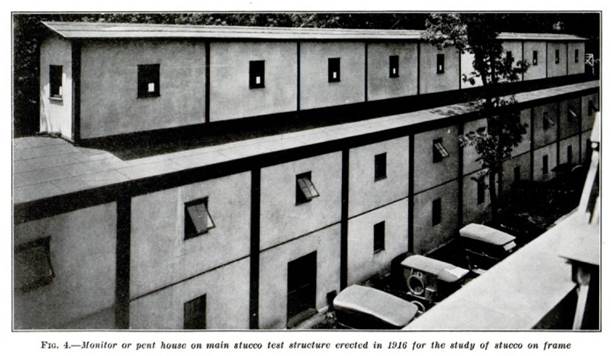
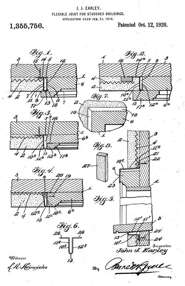
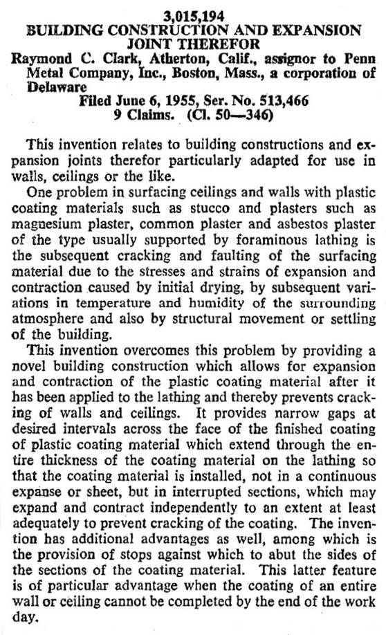
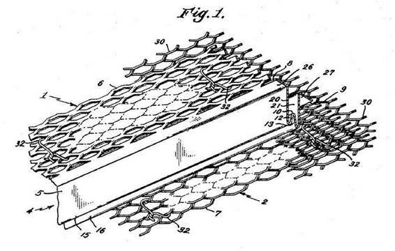
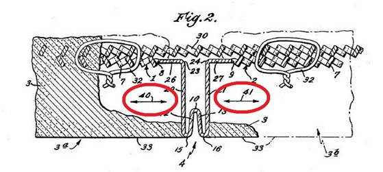
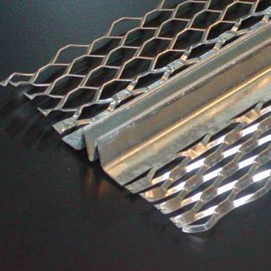
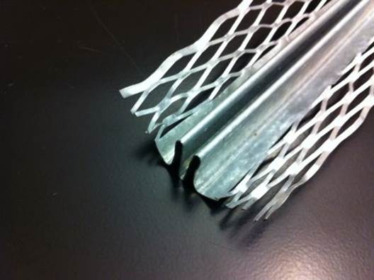
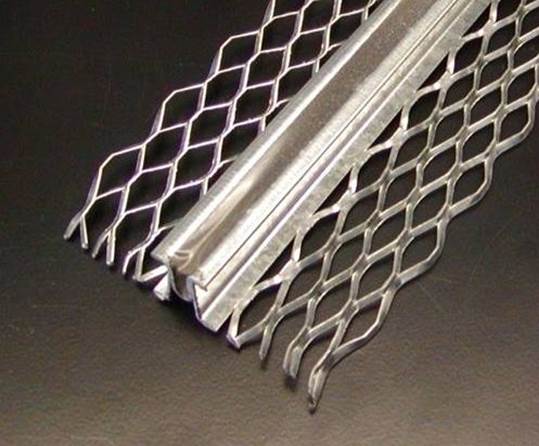
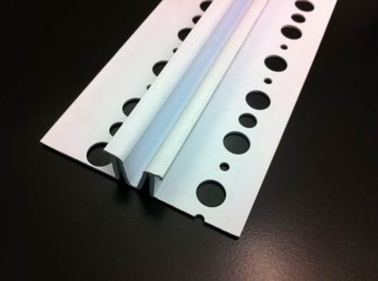
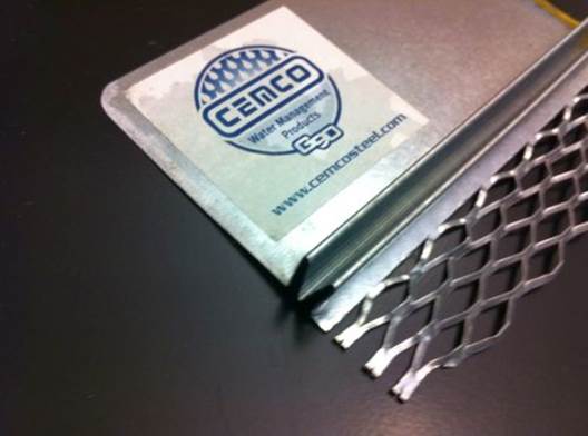
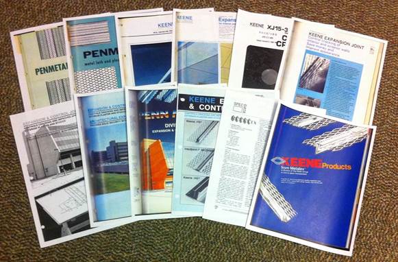
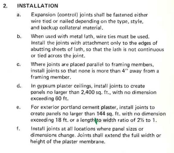
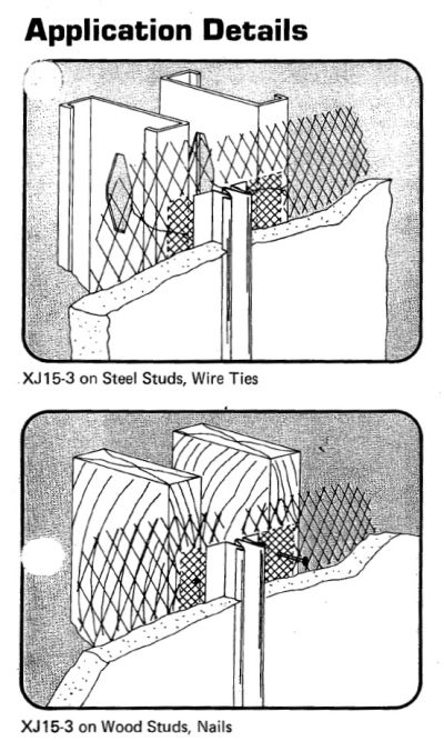
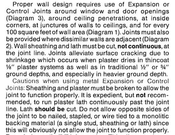
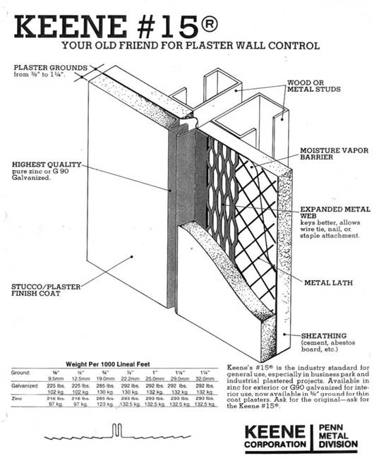
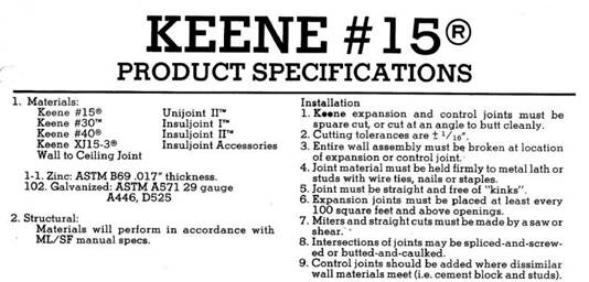
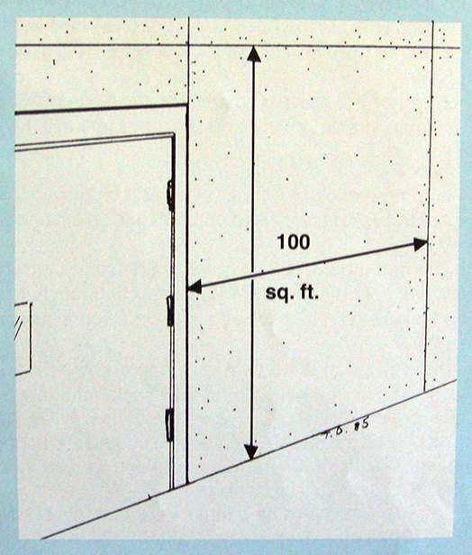
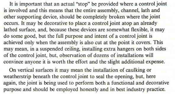
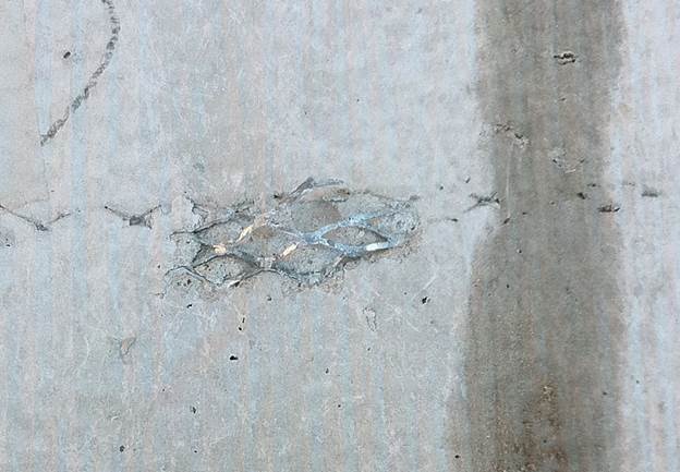
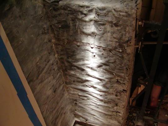
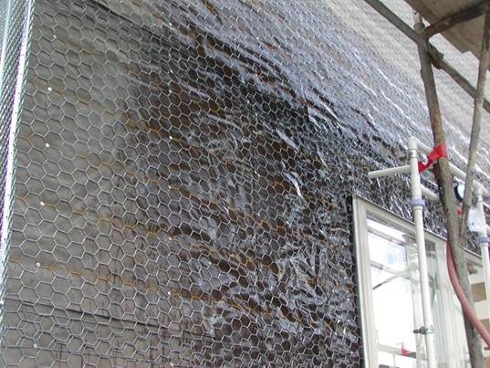
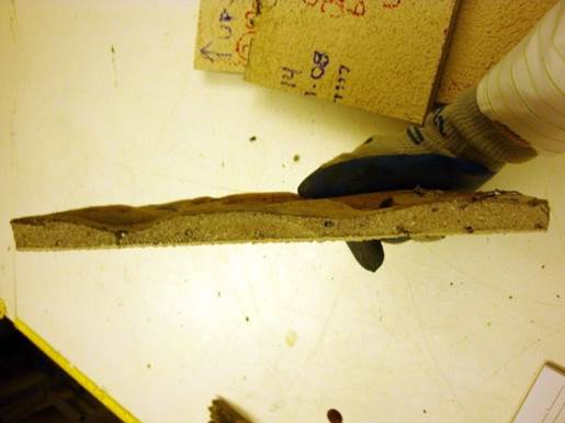
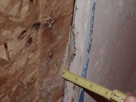
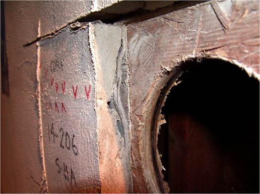
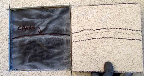
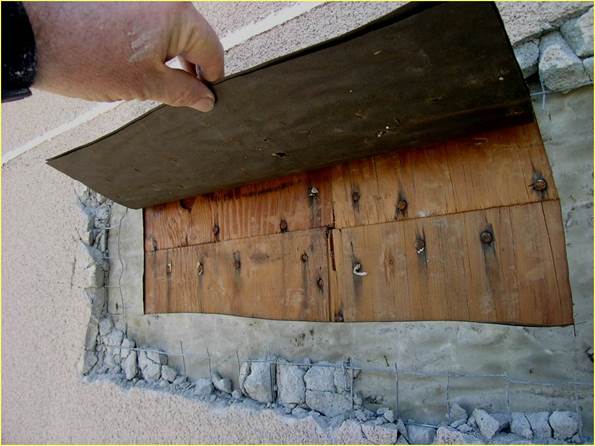
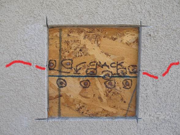
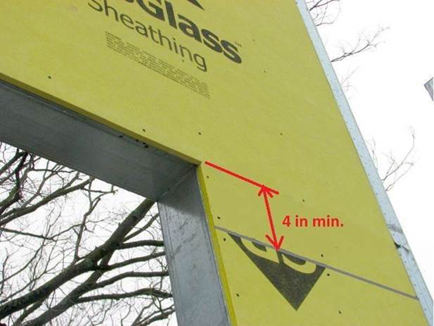
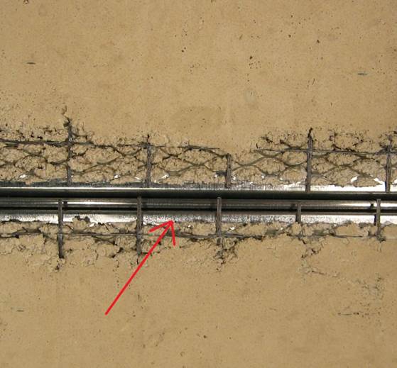
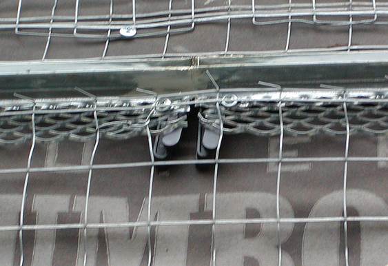
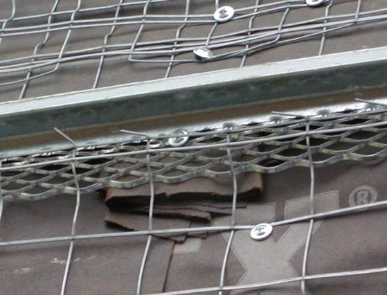
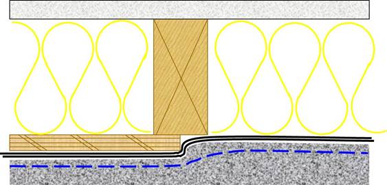
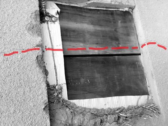
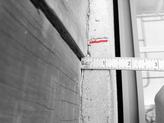
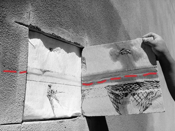
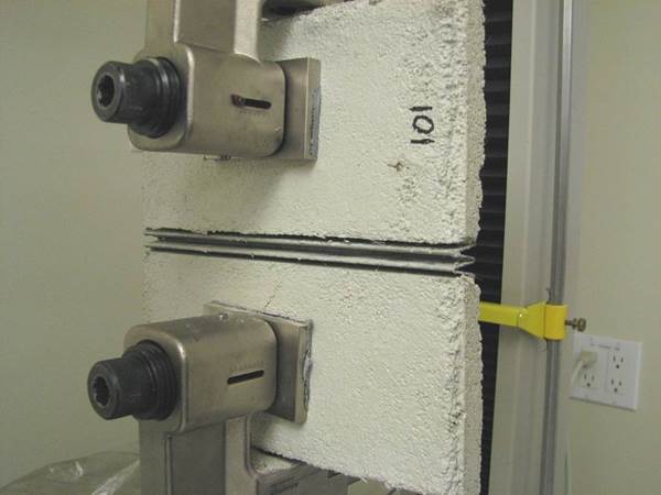
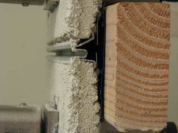
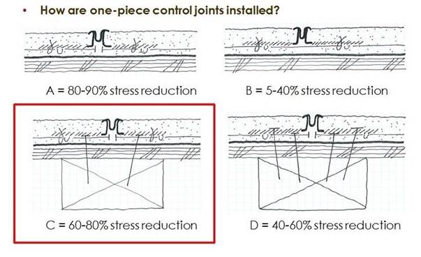
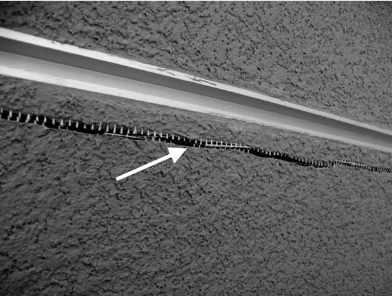
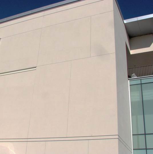

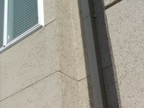
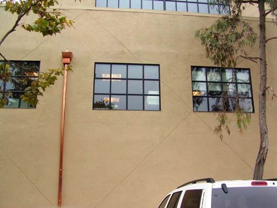
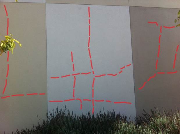
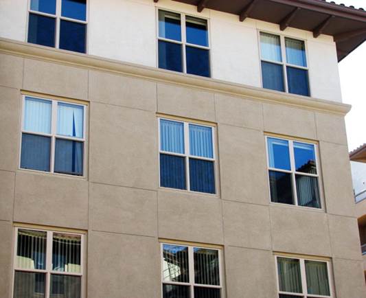
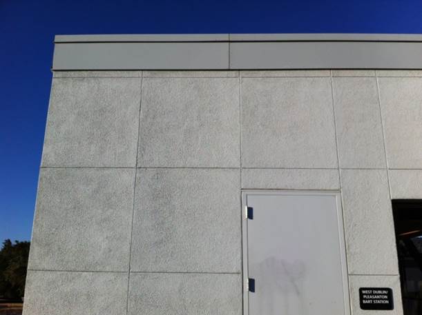
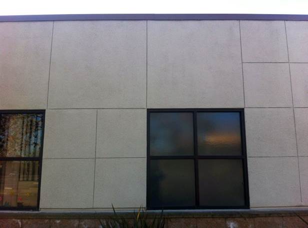
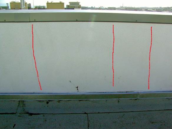

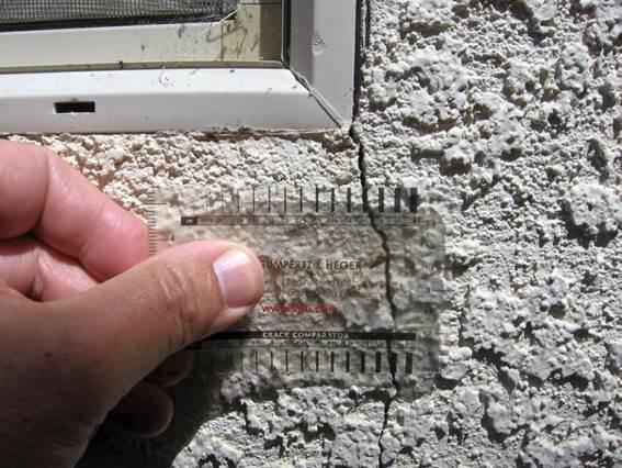
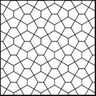
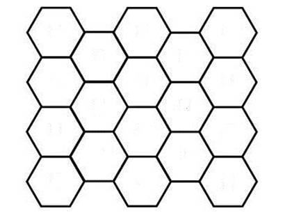
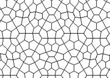
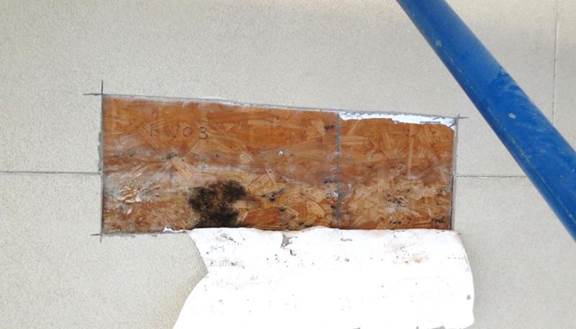
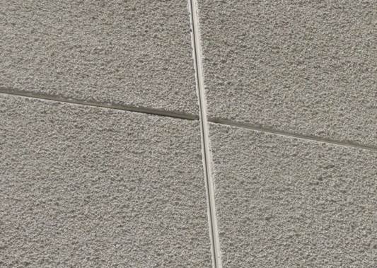
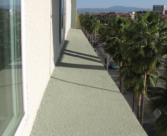
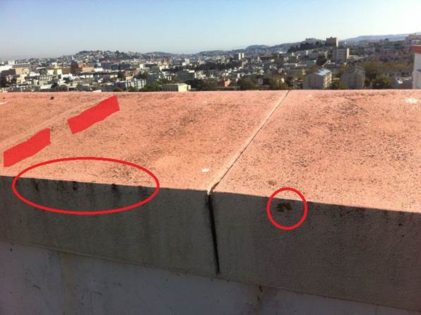
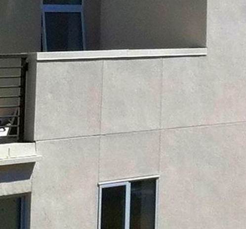
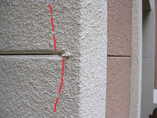

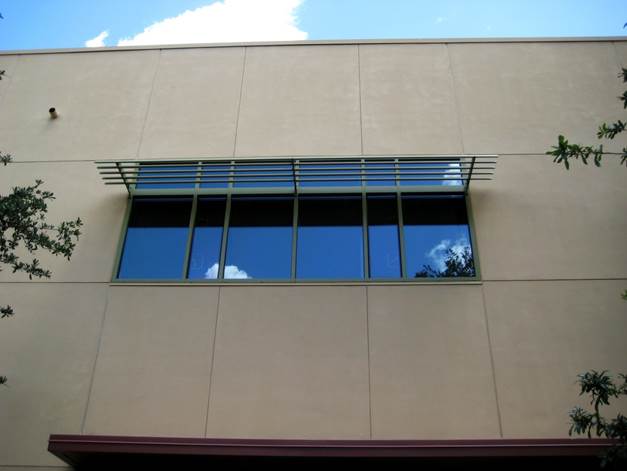
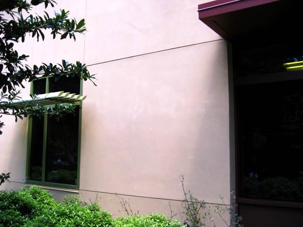

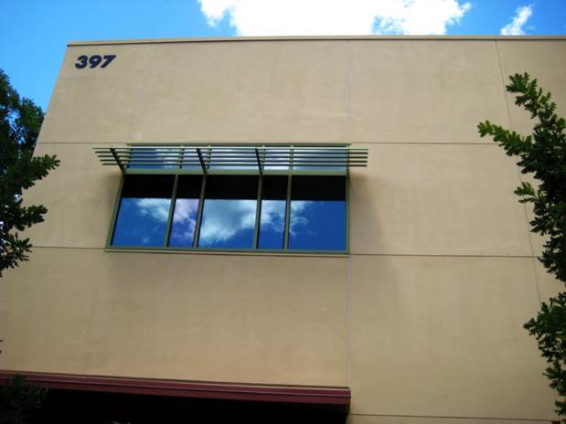
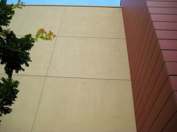
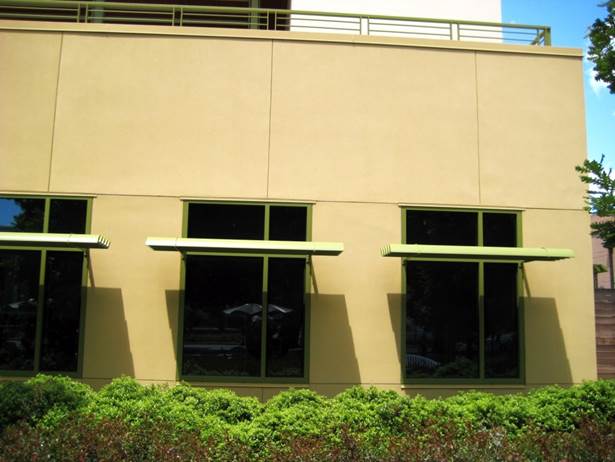
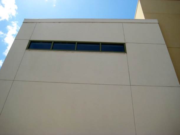
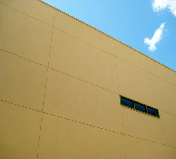
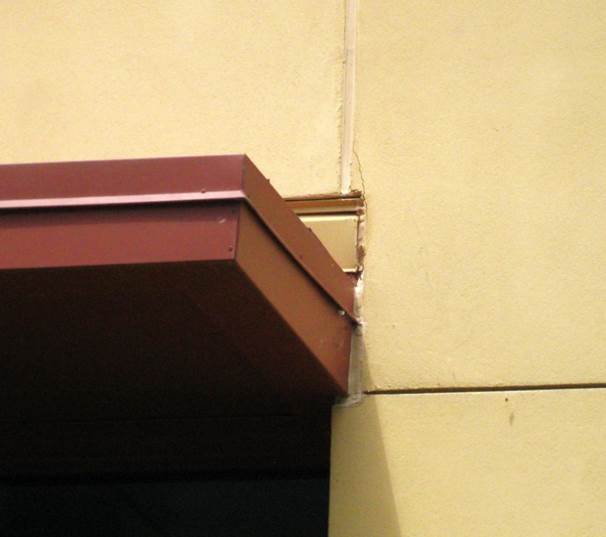
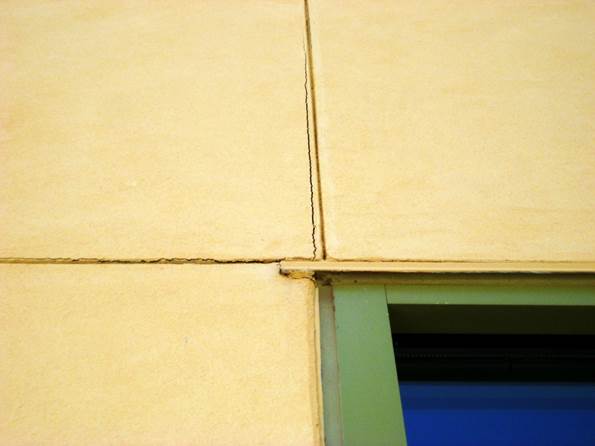
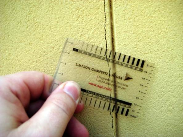

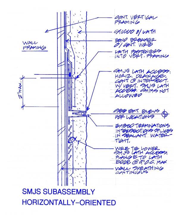
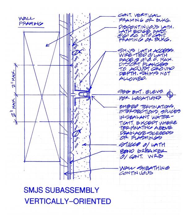
Home Page Contact Me Disclaimer